Insulating concrete form

a concrete form and insulation technology, applied in the direction of walls, constructions, building components, etc., can solve the problems of affecting the shape size, affecting the appearance, and subjecting the tie to considerable force, and none of the ties in the prior art provide some or all of these features

Inactive Publication Date: 2008-01-31
AIRLITE PLASTICS
View PDF52 Cites 29 Cited by
  • Summary
  • Abstract
  • Description
  • Claims
  • Application Information

AI Technical Summary

Problems solved by technology

However, because of the bulk of ICFs, in general, a countervailing consideration with respect to the size of the form is the shipping costs.
As wet concrete is poured, the concrete, particularly on the forms at the lowest level of the hollow wall, subjects the tie to considerable force by pushing the two panels away from one another.
None of the ties in the prior art provide some or all of these features.

Method used


Image

  • Insulating concrete form
  • Insulating concrete form
  • Insulating concrete form

Examples


Embodiment Construction

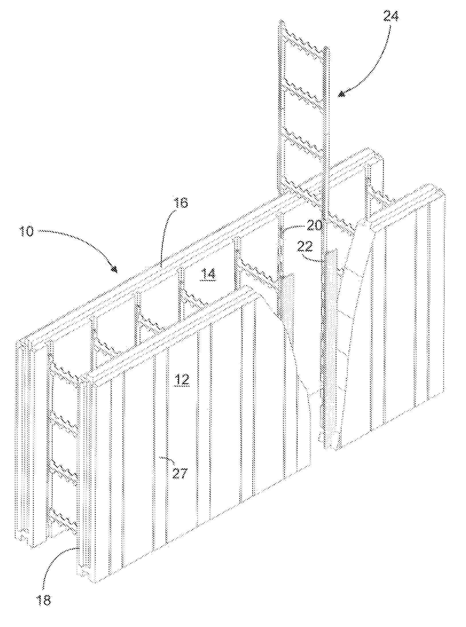
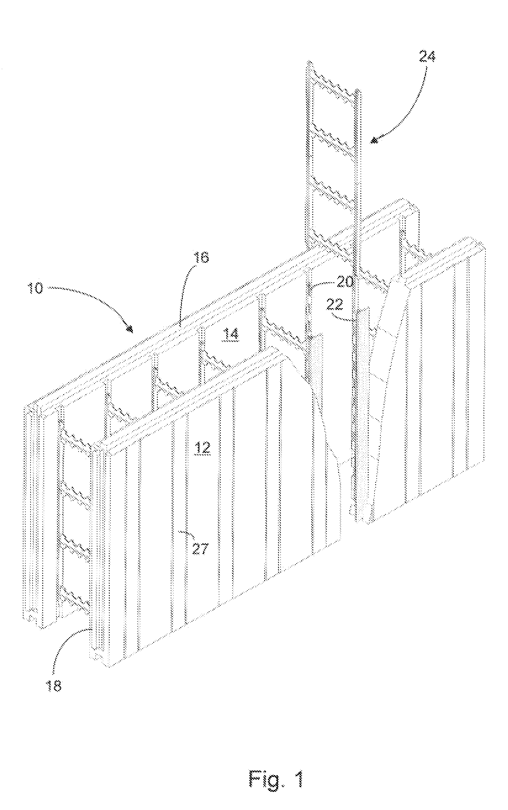
[0023]FIG. 1 illustrates one embodiment of an ICF in a fully assembled condition except for one tie which is positioned above the form in readiness for assembly into the form. The form 10 comprises a first panel 12 and a second panel 14 shown in spaced-apart relationship so as to define an inner space and constructed of lightweight material such as expanded polystyrene. Each panel has an upper edge 16 and a lower edge (not shown). Each panel also has an end 18 and an opposite end (not shown). The ends and / or upper and lower edges of each panel may be provided with a tongue and groove design so that the panels may be interlocked as the hollow wall comprising multiple ICFs is built.

[0024] A tie assembly comprises a pair of anchors 20, 22 fixedly attached to the respective panels as by embedding the anchors in the panel walls during formation of the panels. It will be understood by those having ordinary skill in the art that the anchors may protrude inwardly from the panel inner surfa...


PUM


Abstract

A knocked-down insulating concrete form including two spaced apart lightweight panels maintained in position by a tie assembly.

Description

CROSS-REFERENCE TO RELATED APPLICATION [0001] This application claims the benefit of the filing of U.S. Provisional Application Ser. No. 60 / 758,241, entitled Insulating Concrete Form filed on Jan. 11, 2006 and the specification thereof is incorporated herein by reference.BACKGROUND OF THE INVENTION [0002] The use of Insulating Concrete Forms (ICFs) is well accepted as a superior building construction technology. Briefly, an ICF is an expanded plastic, usually polystyrene, form comprising two spaced apart panels. The forms are assembled into a hollow vertical wall into which concrete is poured thereby creating a concrete wall. Unlike wood or steel forms, the ICF remains in place and becomes a permanent part of the building providing insulation that contributes to energy efficiency, lower noise, and environmentally responsible practices. There are a large number of design considerations for ICFs not the least of which is ease in constructing the hollow vertical wall with minimum labor...

Claims


Application Information

Patent Timeline
Patent Type & Authority Applications(United States)
IPC IPC(8): E04B2/10E04B2/08
CPCE04B2/8641
Inventor SCHERRER, EDWARD
Owner AIRLITE PLASTICS
Why Eureka
Try Eureka