Constant Flow Regulator Device

a constant flow and regulator technology, applied in the direction of valve operating means/releasing devices, process and machine control, instruments, etc., can solve the problems of reliability and endurance, relatively expensive devices to produce, and previously known fluid flow regulator devices having several different interacting parts. achieve the effect of simple yet reliable and accura

Inactive Publication Date: 2008-01-31
AEROCRINE AB
View PDF10 Cites 2 Cited by
  • Summary
  • Abstract
  • Description
  • Claims
  • Application Information

AI Technical Summary

Benefits of technology

[0004] It is an object of the present invention to address the problems above and to provide a simple yet reliable and accurate constant flow regulator device.

Problems solved by technology

Previously known fluid flow regulator devices are relatively complex devices having several different interacting parts, such as springs, diaphragms, valves and valve seats.
These devices are relatively costly to produce, both due to the many parts required which need to be manufactured with high precision, and also due to high assembly costs.
Other problems with previously known devices are related to reliability and endurance.
However, this regulator is designed for creating a constant fluid pressure and cannot be used for creating a constant fluid flow.

Method used


Image

  • Constant Flow Regulator Device
  • Constant Flow Regulator Device
  • Constant Flow Regulator Device

Examples


first embodiment

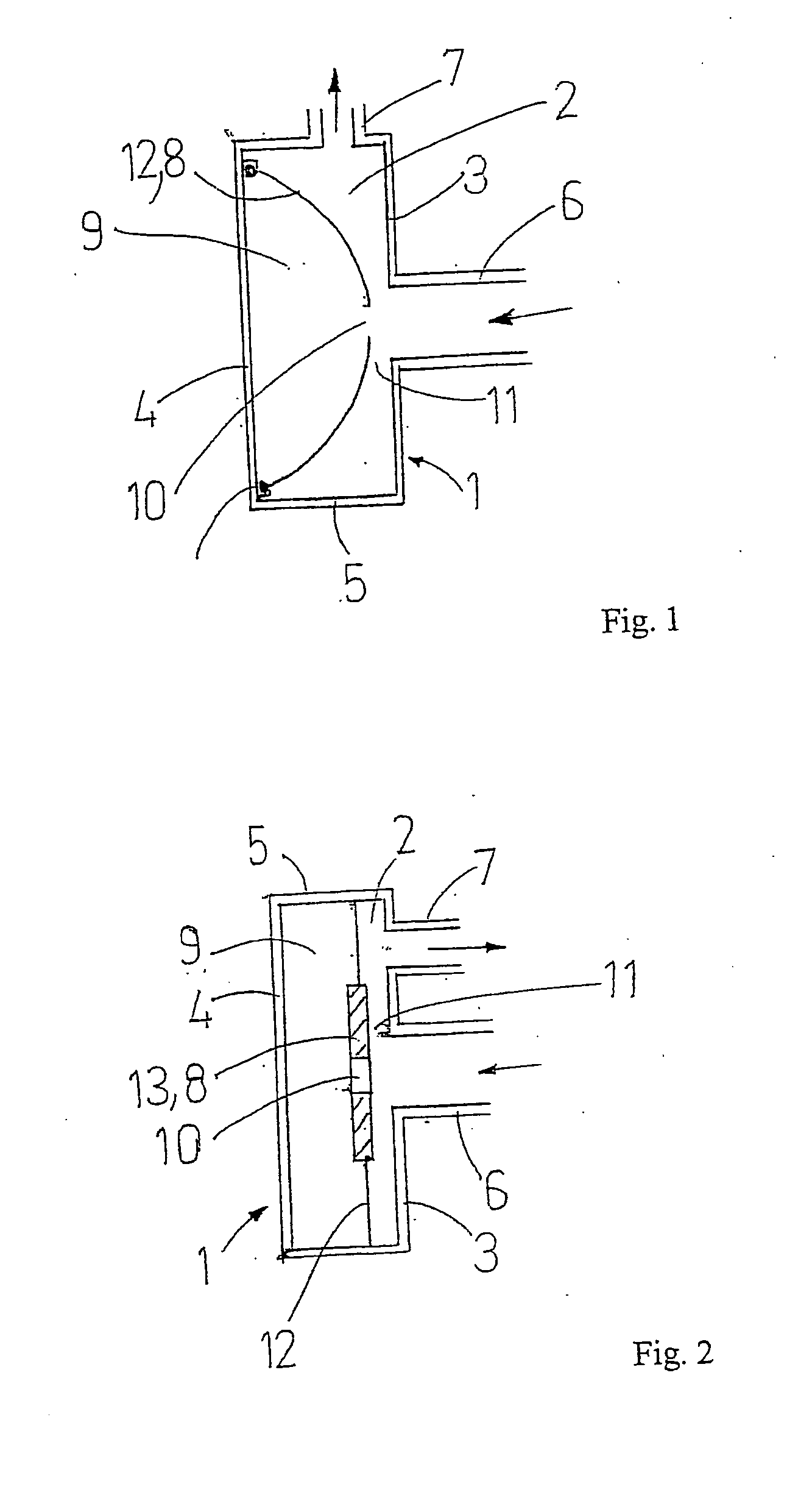
[0026] shown in FIG. 1, an inner compartment 9 is formed by arranging a movable partition 8 inside the chamber 2, which together with the second wall 4 makes up the inner compartment. The partition 8 is made of a resilient material such as rubber or other polymer. The inner compartment, preferably at the movable partition 8, is provided with an aperture 10 preferably somewhere in a central part of the movable partition 8, for fluid communication between the inlet duct and the inner compartment. The inlet duct 6 is also arranged somewhere in the central part of the first wall 3, and thus roughly opposite the aperture 10 in the movable partition 8. However, the inlet duct 6 and the aperture 10 do not need to be aligned, as long as the aperture 10 is located in the vicinity of a high pressure area of the incoming fluid at the inlet duct 6. The inner compartment 9 may not need to have any volume when the pressure of the inlet medium is low, but may expand and thus display a volume when...

fourth embodiment

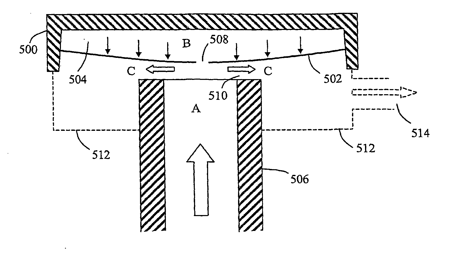
[0036] In FIG. 5, the inventive constant flow regulator device is illustrated, which will be used for explaining the basic mechanism of the present invention in more detail below.

[0037] A housing 500 and a movable partition made as a resilient diaphragm 502 form an inner compartment 504 arranged in a fixed relationship with an inlet duct 506 for incoming fluid, the diaphragm 502 facing the inlet duct 506. The size of the diaphragm 502 is significantly greater than the size of the inlet duct 506, the latter constituting a high pressure zone when a fluid pressure is applied in the inlet duct 506 that is the sum of a static pressure and a dynamic pressure. The diaphragm 502 has an aperture 508 in the vicinity of the inlet duct 506, providing fluid communication between the incoming fluid and the inner compartment 504. Thereby, a relatively high static fluid pressure at “A” in the inlet duct 506 is basically also present at “B” inside the inner compartment 504 by means of the aperture 5...

sixth embodiment

[0044]FIG. 7 illustrates a front view of an inlet duct 700 of a constant flow regulator device which may be arranged on the end of the inlet duct 506, 602 of FIGS. 5 and 6, or just inside the inlet opening 6 shown in FIGS. 1-4. A plurality of protruding knobs or ribs 702 are arranged on the end surface around the inlet duct or opening facing the movable partition, in order to eliminate the risk of closing the fluid passage 11 or 510 completely if an excessive fluid pressure would move the movable partition into contact with the inlet duct or opening. Moreover, the protruding knobs or ribs 702 may optionally be used to further influence the characteristics of said elastic force, e.g. in combination with the selection of material and / or thickness of resilient part(s) of the movable partition.

[0045] In FIG. 8, a seventh embodiment of the inventive constant flow regulator device is illustrated which is different from the previous embodiments 1-6 by using a rigid movable partition 800 w...


PUM


Abstract

A constant flow regulator device for maintaining a constant flow of fluid when a variable fluid pressure is applied, comprising an inlet duct ( 506 ) for incoming fluid, a housing ( 500 ), and a movable partition ( 502 ) facing the inlet duct and being subjected to an elastic force. A fluid passage ( 510 ) of variable cross section area is formed between the inlet duct and the movable partition. The housing and movable partition form an inner compartment ( 504 ) in fluid communication with the inlet duct for establishing a fluid pressure inside the inner compartment approximately equal to the fluid pressure in the inlet duct. The size of the movable partition is significantly greater than the size of the inlet duct such that, in use, the partition is moved towards the inlet duct against the elastic force when the fluid pressure in the inlet duct increases to reduce said fluid passage cross section area, and vice versa, thereby maintaining constant fluid flow.

Description

[0001] The present invention relates generally to a constant flow regulator device for maintaining a constant flow of fluid when a variable fluid pressure is applied, preferably a flow of gas or gas mixture. The fluid flow may be measured in ml / s. In particular, the inventive constant flow regulator device is configured to maintain the fluid flow substantially constant regardless of the applied fluid pressure, at least within a certain operating range. BACKGROUND ART [0002] Previously known fluid flow regulator devices are relatively complex devices having several different interacting parts, such as springs, diaphragms, valves and valve seats. These devices are relatively costly to produce, both due to the many parts required which need to be manufactured with high precision, and also due to high assembly costs. Other problems with previously known devices are related to reliability and endurance. [0003] U.S. Pat. No. 3,463,182 discloses a constant pressure fluid regulator where a ...

Claims


Application Information

Patent Timeline
Patent Type & Authority Applications(United States)
IPC IPC(8): F16K17/34
CPCF15C3/04G05D7/012F16K31/385F16K17/34G05D7/0113Y10T137/0396Y10T137/7754Y10T137/8593
Inventor BAHRTON, SVANTE
Owner AEROCRINE AB
Why Eureka
Try Eureka