

Side-by-side ATV
a technology of side-by-side atvs and atvs, which is applied in the directions of vehicle arrangement, transportation and packaging, and mounting of jet propulsion devices, etc., can solve the problems of inacceptable or impractical use of most side-by-side atvs on trails
- Summary
- Abstract
- Description
- Claims
- Application Information
AI Technical Summary
Problems solved by technology
Method used
Image

Examples
Embodiment Construction
[0038]The embodiments disclosed below are not intended to be exhaustive or to limit the invention to the precise forms disclosed in the following detailed description. Rather, the embodiments are chosen and described so that others skilled in the art may utilize their teachings. For example, while the following description refers primarily to a ATV, certain features described herein may be applied to other applications such as UVs, snowmobiles, motorcycles, mopeds, etc.
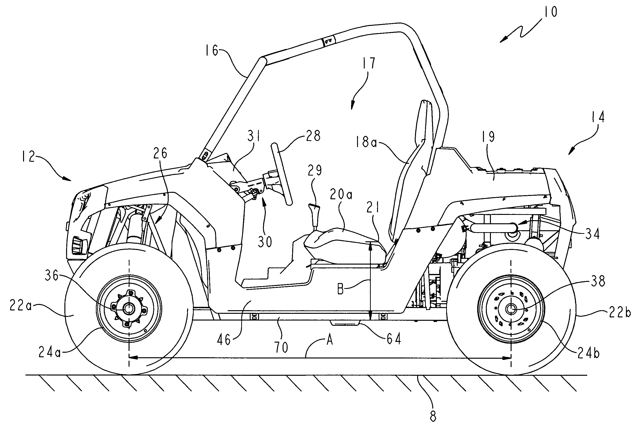
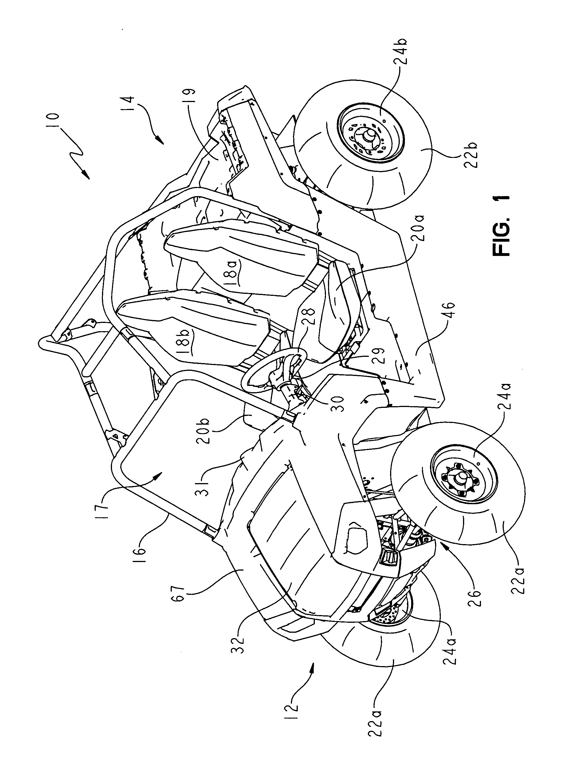
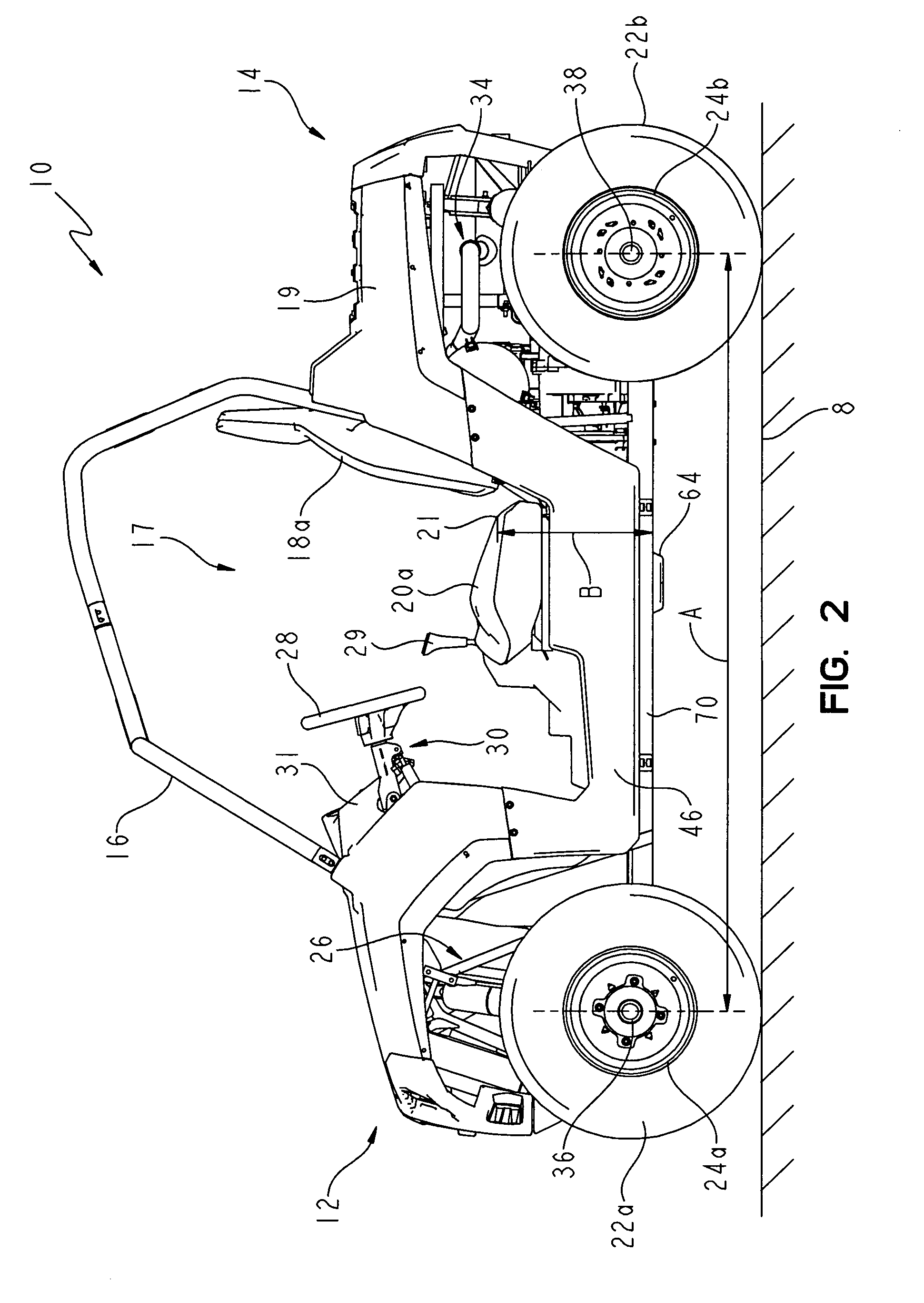
[0039]Referring initially to FIG. 1, one illustrative embodiment of side-by-side ATV 10 is shown. ATV 10 includes front end 12 and rear end 14, and a frame 15 which is supported above the ground surface by a pair of front tires 22a and wheels 24a and a pair of rear tires 22b and wheels 24b. ATV 10 includes a pair of laterally spaced-apart upper and lower seating surfaces 18a, 18b and 20a, 20b, respectively. The upper seating surfaces 18a, 18b are configured to support the backs of sitting riders, while the lower seati...
PUM
 Abstract
Description
Claims
Application Information