
Automatic auxiliary lighting unit

a technology of automatic auxiliary lighting and lighting units, which is applied in the field of light sources, can solve the problems of difficult and hazardous search for backup lighting after a power failure, and achieve the effects of convenient light source, convenient use, and convenient us

Inactive Publication Date: 2008-01-31
ROMANO JOHN
View PDF13 Cites 23 Cited by
  • Summary
  • Abstract
  • Description
  • Claims
  • Application Information

AI Technical Summary

Benefits of technology

[0007]A significant advantage of this invention is that the lighting unit avoids the hassles and dangers associated with a sudden power outage that eliminates all wired light sources in a residence. Furthermore, the lighting unit is versatile, convenient and easy to use, lightweight yet durable in design, and provides a user with a convenient light source in the event of a power outage.

Problems solved by technology

Unless previously set aside in a location easily accessible in the dark, a search for backup lighting after a power failure can be difficult and hazardous.

Method used


Image

  • Automatic auxiliary lighting unit
  • Automatic auxiliary lighting unit
  • Automatic auxiliary lighting unit

Examples


Embodiment Construction

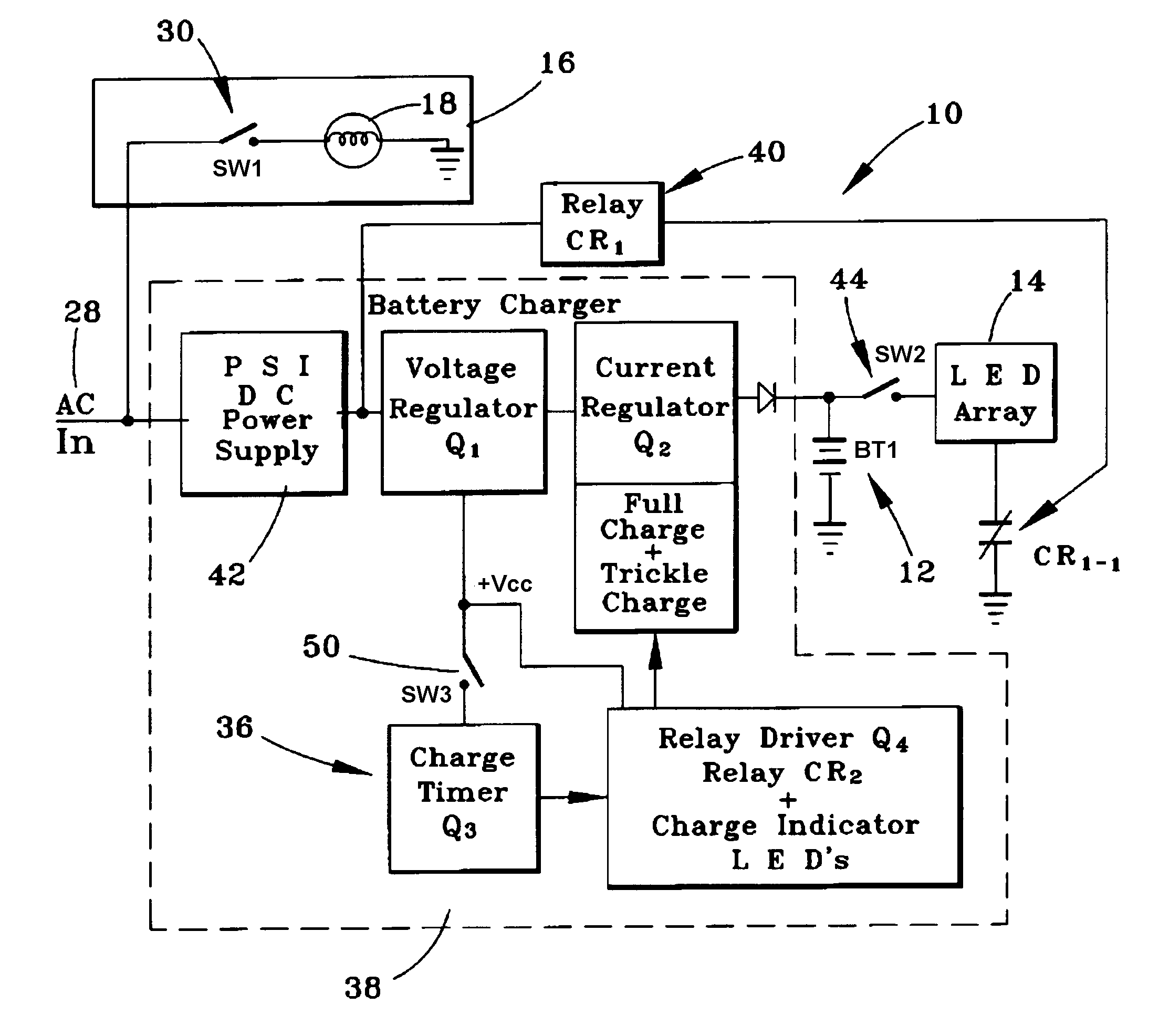
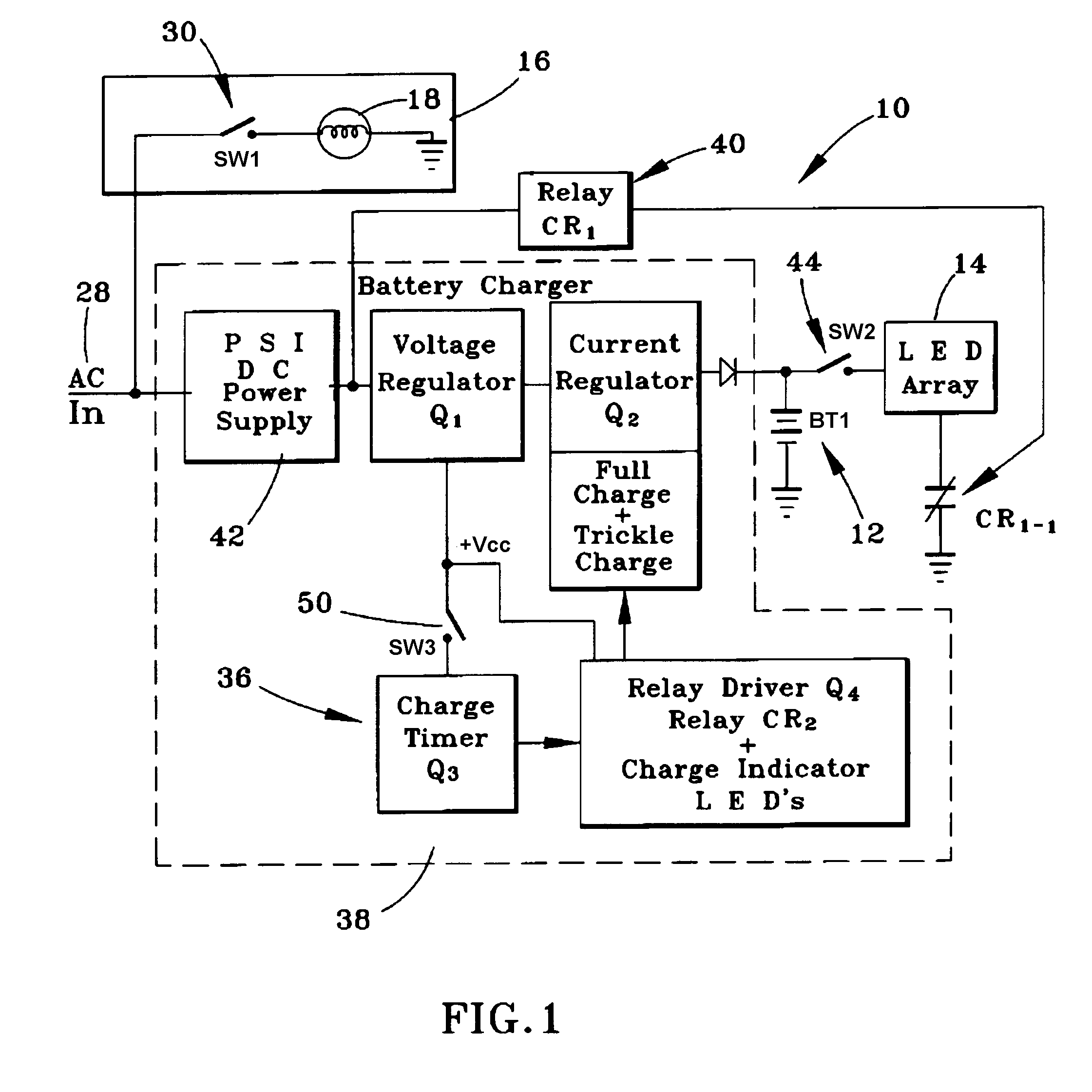
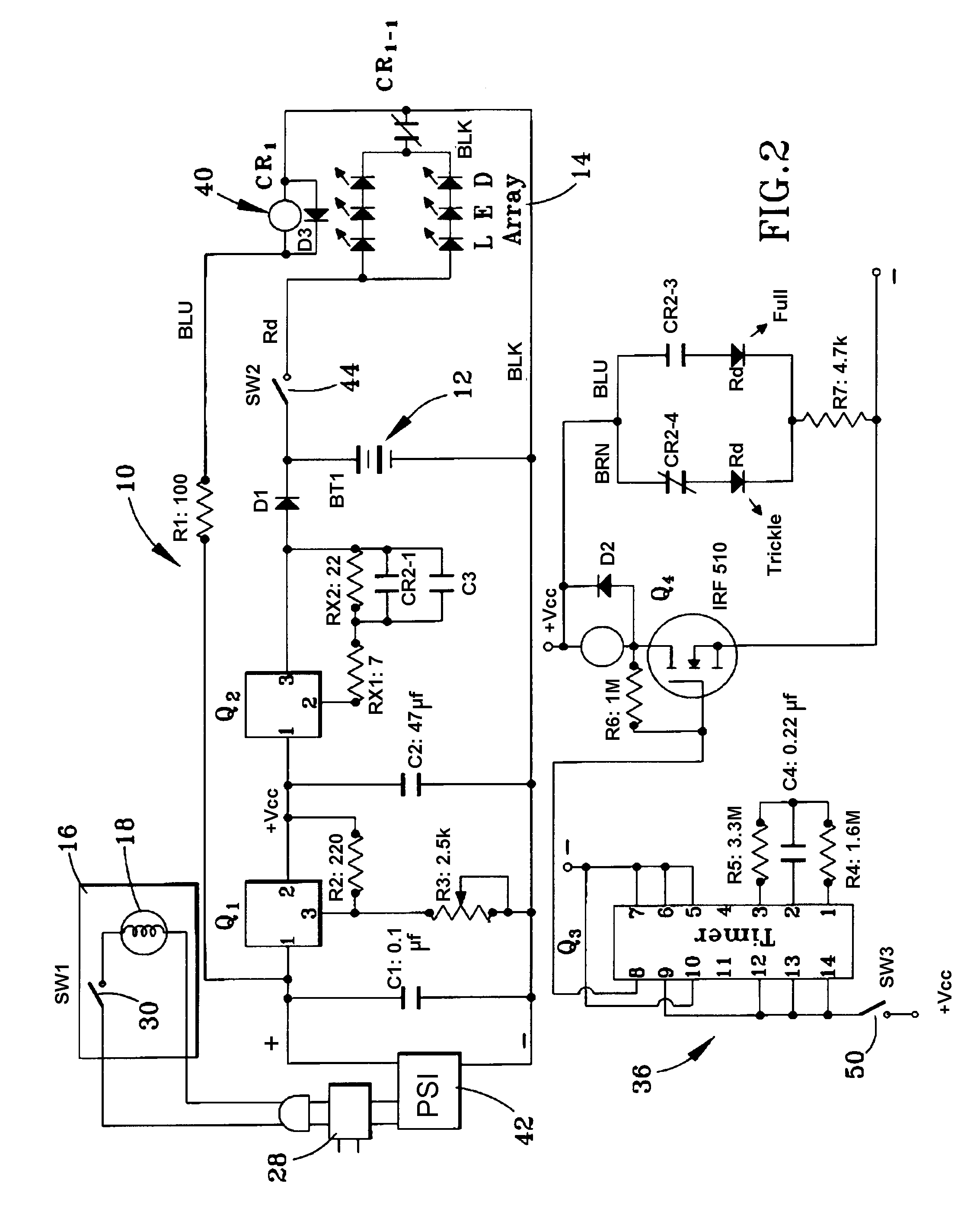
[0013]FIGS. 1 and 2 schematically represent the most basic components preferred for the operation and use of an automatic auxiliary lighting unit 10 of this invention. The lighting unit 10 comprises a battery 12 and a battery-operated LED (light-emitting diode) light source 14. The lighting unit 10 is represented as adapted for use with a lamp 16, such as a desk lamp or floor lamp, equipped with a light source 18, such as a conventional AC-powered incandescent bulb or a fluorescent bulb, though other lamp configurations and bulb configurations are possible.

[0014]Three configurations for implementation of the lighting unit 10 with or without the lamp 16 are represented in FIGS. 3 through 5. Because of similarities between the embodiments of FIGS. 3 through 5, consistent reference numbers are used in the Figures to identify functionally similar structures. FIG. 3 generically represents a suitable configuration for the lamp 16 as including a lamp pole 20 supported by a base 22, with it...


PUM


Abstract

A lighting unit having a battery-powered auxiliary light source that is automatically powered in the event of a power outage. The lighting unit can be an integral portion of a lamp, configured as an add-on to an existing lamp, or configured as a standalone light source. The lighting unit includes a device for rectifying AC power supplied to the unit to generate DC power, a battery and a device for charging the battery from the AC power, a relay powered by the DC power and with input contacts electrically connected to the battery, and at least one LED light source electrically connected to output contacts of the relay. The relay is configured so that it interrupts current flow from the battery to the LED light source when the DC power is supplied to the relay as a result of AC power being supplied to the rectifying device, and the relay automatically enables current flow from the battery to the LED light source when the DC power to the relay is interrupted as a result of AC power to the rectifying device being interrupted.

Description

CROSS REFERENCE TO RELATED APPLICATIONS[0001]This application claims the benefit of U.S. Provisional Application No. 60 / 820,864, filed Jul. 31, 2006, the contents of which are incorporated herein by reference.BACKGROUND OF THE INVENTION[0002]The present invention generally relates to light sources and, more particularly, to an automatic auxiliary lighting unit suitable for providing users with a light source in the event of a power outage.[0003]The most common artificial light sources currently available for use in residential and commercial buildings are incandescent lamps (including halogen lamps), fluorescent lamps, and high-intensity discharge (HID) lamps. More recently, solid state lighting (SSL) such as LED (light-emitting diode) lamps have become sufficiently powerful to be considered as artificial light sources.[0004]Regardless of what type of light source is used, electricity is required for its operation. In the event of a power interruption to wired light sources due to a...

Claims


Application Information

Patent Timeline
Patent Type & Authority Applications(United States)
IPC IPC(8): H02J7/00H02J7/02H05B37/02
CPCH02J9/02H05B37/0209H05B33/0806H05B45/00H05B45/345H05B47/10
Inventor ROMANO, JOHN
Owner ROMANO JOHN
Learn More