Rotating Armature

a technology of rotating armatures and coils, applied in the direction of dynamo-electric machines, electrical apparatus, commutators, etc., can solve the problems of loose coil windings, and achieve the effect of preventing the coil winding from coming apar

Inactive Publication Date: 2008-01-31
SHOWA CORP
View PDF9 Cites 11 Cited by
  • Summary
  • Abstract
  • Description
  • Claims
  • Application Information

AI Technical Summary

Benefits of technology

[0006]An object of the present invention is to prevent a coil winding from coming apart by simply and securely fixing a wound coil to a bobbin, in a rotating armature.

Problems solved by technology

In the prior art, since each of the wind starting and the wind terminating of the coil is simply inserted to the coil insertion groove provided in the bobbin, there is a risk that each of the wind starting and the wind terminating of the coil comes off from the coil insertion groove and the coil winding comes loose.

Method used


Image

  • Rotating Armature
  • Rotating Armature
  • Rotating Armature

Examples


Embodiment Construction

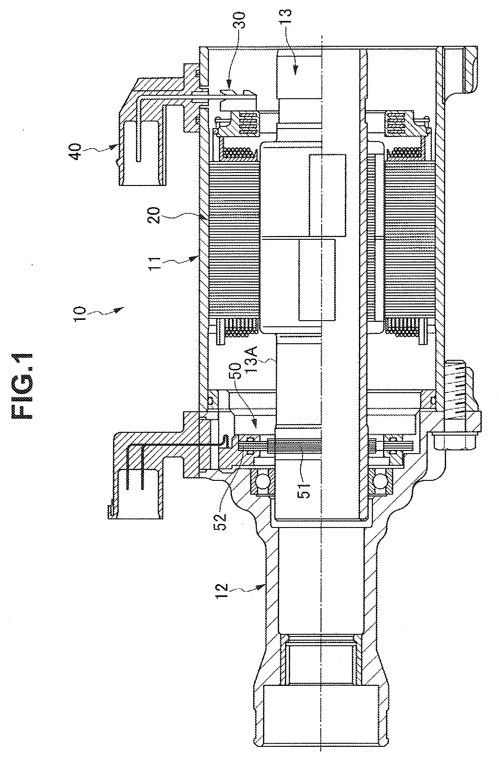
[0021]A DC brushless motor 10 corresponding to a rotating armature in accordance with the present invention is structured, as shown in FIG. 1, such that an end housing 12 is attached to one end of a stator assembly 11, and a rotor assembly 13 is rotatably supported to the stator assembly 11 and an inner portion of the end housing 12.

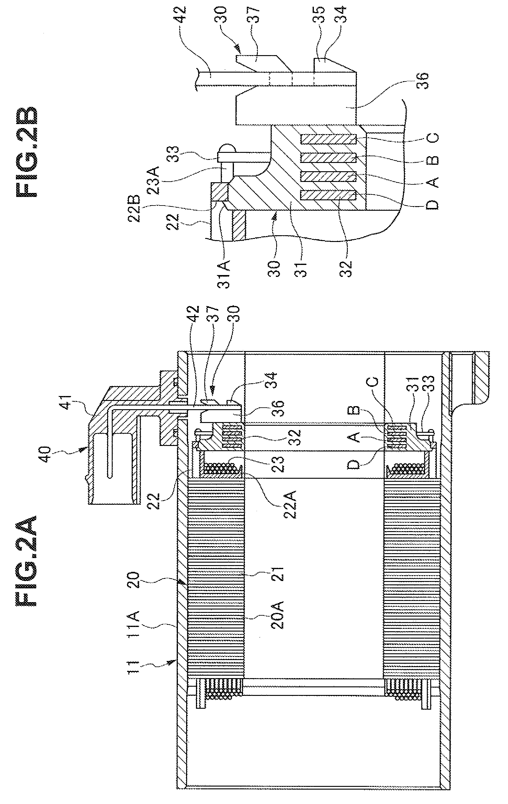
[0022]The stator assembly 11 is structured, as shown in FIGS. 2A to 3B, such that a sub assembly of a cylindrical stator 20 and a terminal 30 is stored in an inner periphery of a yoke integrally formed with the housing 11A, and a coupler 40 attached to the housing 11A is connected to the terminal 30.

[0023]The stator 20 is structured, as shown in FIGS. 4A and 4B, such that a plurality of, for example, four in each of U-phase, V-phase and W-phase (totally twelve) core sub assemblies 20A in the present embodiment, fitted to the inner periphery of the housing 11A are arranged adjacently on a circumference. The core sub assembly 20A is structured by laminatin...


PUM


Abstract

In a rotating armature in which a bobbin is attached to a core constituting a stator, a coil is wound around a coil winding portion of the bobbin, and a wind starting and a wind terminating of the coil are a respectively inserted to coil insertion grooves provided in an outer peripheral side than the coil winding portion in the bobbin, and coil come-off preventing locking portions are provided in the coil insertion grooves of the bobbin.

Description

BACKGROUND OF THE INVENTION[0001]1. Field of the Invention[0002]The present invention relates to a rotating armature.[0003]2. Description of the Related Art[0004]As a rotating armature, there is a structure in which a resin bobbin is attached to a core constituting a stator, a coil is wound around a coil winding portion of the bobbin, each of a wind starting and a wind terminating of the coil is inserted to a coil insertion groove provided in an outer peripheral side than the coil winding portion in the bobbin, and the wound coil is fixed to the bobbin, as described in Japanese Patent Application Laid-open No. 2002-354738 (patent document 1).[0005]In the prior art, since each of the wind starting and the wind terminating of the coil is simply inserted to the coil insertion groove provided in the bobbin, there is a risk that each of the wind starting and the wind terminating of the coil comes off from the coil insertion groove and the coil winding comes loose.SUMMARY OF THE INVENTION...

Claims


Application Information

Patent Timeline
Patent Type & Authority Applications(United States)
IPC IPC(8): H02K21/10
CPCH02K3/522
Inventor SABOI, TAKAHIRONOZAWA, HIROMI
Owner SHOWA CORP
Why Eureka
Try Eureka