Optical transmitter and optical transmission method
a technology of optical transmitter and optical transmission method, which is applied in the direction of electromagnetic transmission, electrical equipment, transmission, etc., can solve the problems of difficult control to keep the optical output constant, the failure of each semiconductor laser unit over its service life, and the inability to detect a performance degradation or failure of each semiconductor laser unit over their service life. , to achieve the effect of accurate monitoring and control
- Summary
- Abstract
- Description
- Claims
- Application Information
AI Technical Summary
Benefits of technology
Problems solved by technology
Method used
Image
Examples
exemplary embodiment 1
Constitution of Optical Transmitter
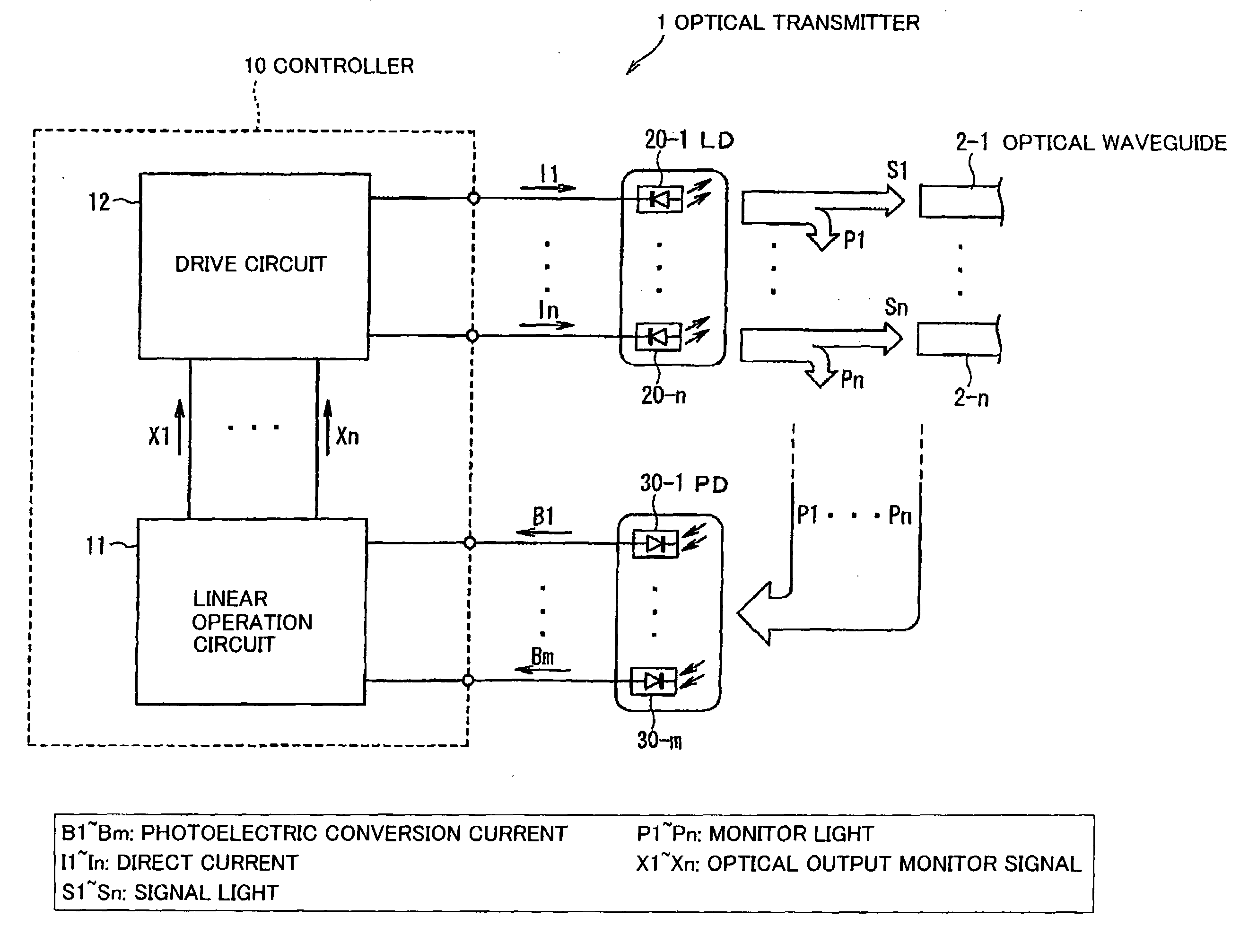
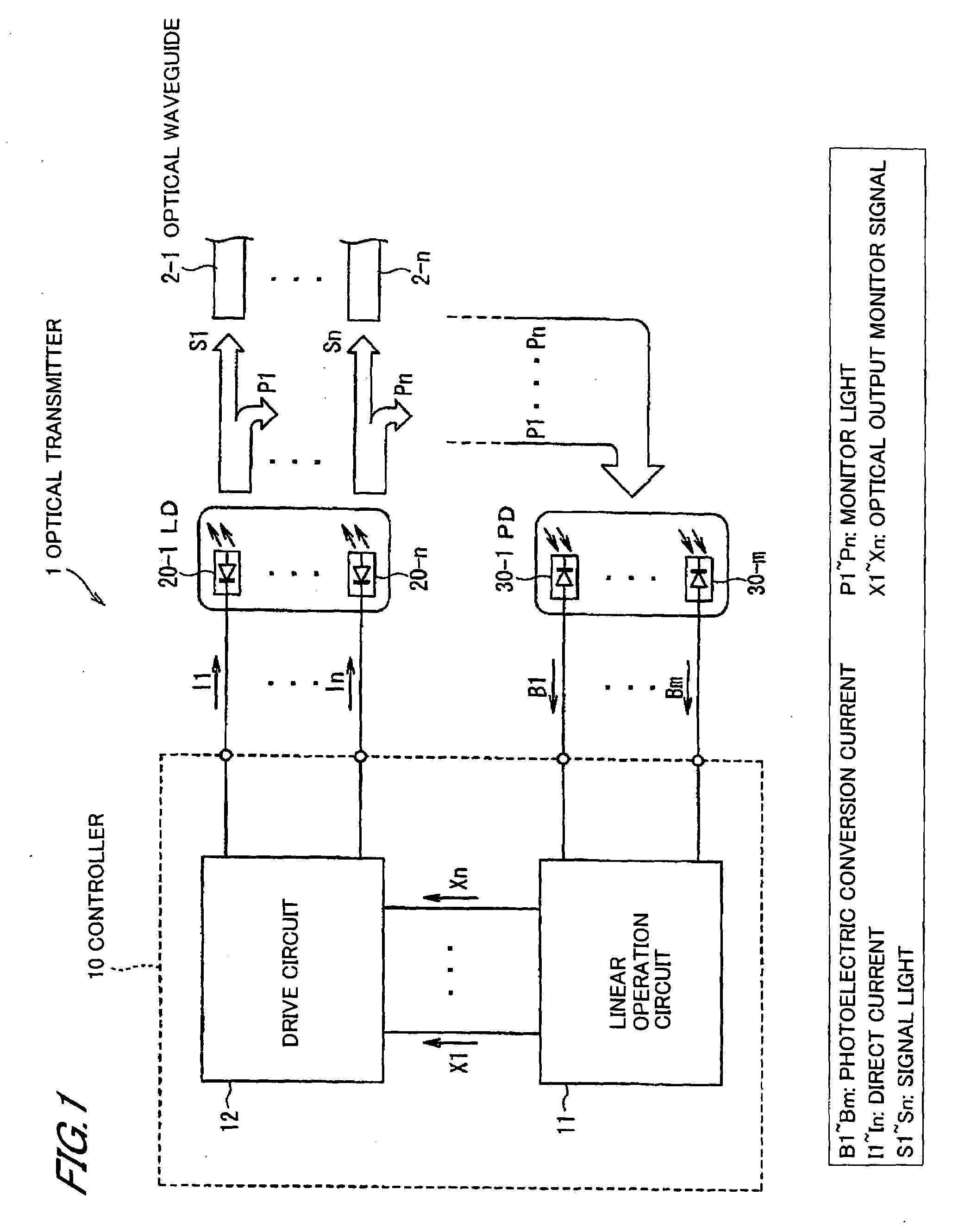
[0030]FIG. 1 shows an optical transmitter in a first exemplary embodiment according to the present invention. The optical transmitter 1 includes a controller 10, laser diodes (LD) 20-1˜20-n as light-emitting elements which are connected to the controller 10, and photo diodes (PD) 30-1˜30-m for monitoring monitor lights P1˜Pn which are optical outputs from the LDs 20-1˜20-n.
[0031]Each of the LDs 20-1˜20-n is connected to n optical waveguides 2-1˜2-n including an optical fiber, a glass optical waveguide, or a polymer optical waveguide, so as to transmit the optical outputs (signal lights S1˜Sn) to a transmission media such as the optical fiber and space.
[0032]A modulation circuit applies a modulation current according to a logic level of n data signals inputted from an external device such as an optical communication apparatus or a computer to the LDs 20-1˜20-n. The modulation circuit is omitted in FIG. 1.
[0033]The LDs 20-1˜20-n can emit light in an...
exemplary embodiment 2
[0065]FIG. 6 shows an optical transmitter 1 in a second exemplary embodiment according to the present invention. The optical transmitter 1 in the second exemplary embodiment includes, as means of recording and communicating, a conversion circuit 16 for converting the optical output monitor signals X1˜Xn to discrete amounts X′1˜X′n which are defined by a predetermined rule, a memory 17 for storing the discrete amounts X′1˜X′n converted by the conversion circuit 16, a comparison circuit 18 for generating warning signals Sa based on the discrete amounts X′1˜X′n, and a memory access interface (I / F) circuit 19 for communicating with an external device 100. The second exemplary embodiment further includes the constitutions of the first exemplary embodiment shown in FIG. 1. In FIG. 6, the optical waveguides 2-1˜2-n are omitted for clarity.
[0066]According to a predetermined rule, the conversion circuit 16, for example, converts the optical output (signal light S) of a real number to an inte...
exemplary embodiment 3
[0073]Configurations of the third exemplary embodiment are the same as the first exemplary embodiment. However, an optical coupling of the PDs 30-1˜30-m and the monitor lights P1˜Pn is designed so as to meet a following expression (4), when designing an implementation of the optical system. (an optical coupling condition of the monitor light and the PD)
[0074]When multiplying n-by-m matrix {Dki} to the equation (2) from left thereof, a following n-by-n simultaneous linear equation is obtained.
ΣjCkjXj=B′k (3)
[0075](k=1, 2, . . . , n, Ckj=ΣiDkiAij, Bi=ΣiDkiBi)
[0076]Therefore, if this n-by-n simultaneous linear equation (3) has a unique solution, the m-by-n simultaneous linear equation (2) also has a unique solution.
[0077]A necessary and sufficient condition for the unique solution of the equation (3) is that the coefficient matrix {Cij} is non-singular. However, when designing the optical system, it is difficult to determine whether the matrix {Cij} is non-singular or not with respect...
PUM
 Abstract
Description
Claims
Application Information
 - R&D
- Intellectual Property
- Life Sciences
- Materials
- Tech Scout
- Unparalleled Data Quality
- Higher Quality Content
- 60% Fewer Hallucinations
Browse by: Latest US Patents, China's latest patents, Technical Efficacy Thesaurus, Application Domain, Technology Topic, Popular Technical Reports.
© 2025 PatSnap. All rights reserved.Legal|Privacy policy|Modern Slavery Act Transparency Statement|Sitemap|About US| Contact US: help@patsnap.com


