Optical transmitter and optical transmission method

a technology of optical transmitter and optical transmission method, which is applied in the direction of electromagnetic transmission, electrical equipment, transmission, etc., can solve the problems of difficult control to keep the optical output constant, the failure of each semiconductor laser unit over its service life, and the inability to detect a performance degradation or failure of each semiconductor laser unit over their service life. , to achieve the effect of accurate monitoring and control

Inactive Publication Date: 2012-07-10
HITACHI METALS LTD
View PDF10 Cites 9 Cited by
  • Summary
  • Abstract
  • Description
  • Claims
  • Application Information

AI Technical Summary

Benefits of technology

[0018]According to the present invention, even if the monitor light is inputted to the light-receiving element from the adjacent light-emitting elements other than the light-emitting element corresponding to the light-receiving element, the crosstalk parts can be removed by the linear operation circuit, and the monitor light from the proper light-emitting element can be accurately monitored and controlled.

Problems solved by technology

However, according to the conventional structures, since the optical outputs of the multiple semiconductor laser units are not detected individually, when there is a variation of a thermal characteristic between the multiple semiconductor laser units, it is difficult to control exactly to keep the optical outputs constant.
Further, since the optical outputs of the multiple semiconductor laser units are not detected individually, it is impossible to detect a performance degradation or a failure of each semiconductor laser unit over their service life.

Method used


Image

  • Optical transmitter and optical transmission method
  • Optical transmitter and optical transmission method
  • Optical transmitter and optical transmission method

Examples


exemplary embodiment 1

Constitution of Optical Transmitter

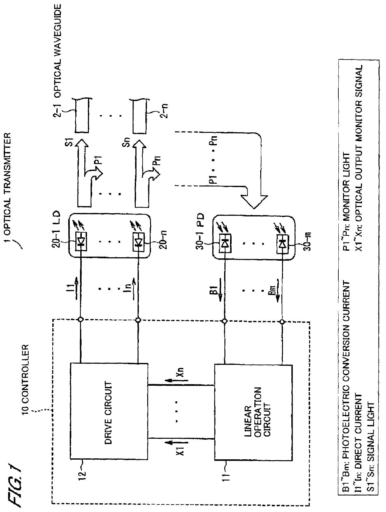
[0030]FIG. 1 shows an optical transmitter in a first exemplary embodiment according to the present invention. The optical transmitter 1 includes a controller 10, laser diodes (LD) 20-1˜20-n as light-emitting elements which are connected to the controller 10, and photo diodes (PD) 30-1˜30-m for monitoring monitor lights P1˜Pn which are optical outputs from the LDs 20-1˜20-n.

[0031]Each of the LDs 20-1˜20-n is connected to n optical waveguides 2-1˜2-n including an optical fiber, a glass optical waveguide, or a polymer optical waveguide, so as to transmit the optical outputs (signal lights S1˜Sn) to a transmission media such as the optical fiber and space.

[0032]A modulation circuit applies a modulation current according to a logic level of n data signals inputted from an external device such as an optical communication apparatus or a computer to the LDs 20-1˜20-n. The modulation circuit is omitted in FIG. 1.

[0033]The LDs 20-1˜20-n can emit light in an...

exemplary embodiment 2

[0065]FIG. 6 shows an optical transmitter 1 in a second exemplary embodiment according to the present invention. The optical transmitter 1 in the second exemplary embodiment includes, as means of recording and communicating, a conversion circuit 16 for converting the optical output monitor signals X1˜Xn to discrete amounts X′1˜X′n which are defined by a predetermined rule, a memory 17 for storing the discrete amounts X′1˜X′n converted by the conversion circuit 16, a comparison circuit 18 for generating warning signals Sa based on the discrete amounts X′1˜X′n, and a memory access interface (I / F) circuit 19 for communicating with an external device 100. The second exemplary embodiment further includes the constitutions of the first exemplary embodiment shown in FIG. 1. In FIG. 6, the optical waveguides 2-1˜2-n are omitted for clarity.

[0066]According to a predetermined rule, the conversion circuit 16, for example, converts the optical output (signal light S) of a real number to an inte...

exemplary embodiment 3

[0073]Configurations of the third exemplary embodiment are the same as the first exemplary embodiment. However, an optical coupling of the PDs 30-1˜30-m and the monitor lights P1˜Pn is designed so as to meet a following expression (4), when designing an implementation of the optical system.

(an optical coupling condition of the monitor light and the PD)

[0074]When multiplying n-by-m matrix {Dki} to the equation (2) from left thereof, a following n-by-n simultaneous linear equation is obtained.

ΣjCkjXj=B′k  (3)

[0075](k=1, 2, . . . , n, Ckj=ΣiDkiAij, Bi=ΣiDkiBi)

[0076]Therefore, if this n-by-n simultaneous linear equation (3) has a unique solution, the m-by-n simultaneous linear equation (2) also has a unique solution.

[0077]A necessary and sufficient condition for the unique solution of the equation (3) is that the coefficient matrix {Cij} is non-singular. However, when designing the optical system, it is difficult to determine whether the matrix {Cij} is non-singular or not with respect ...


PUM


Abstract

An optical transmitter and an optical transmission method includes a plurality of light-emitting elements, a plurality of light-receiving elements for monitoring optical outputs from the light-emitting elements, a linear operation circuit for calculating optical output monitor signals by removing crosstalk parts from a plurality of photoelectric conversion currents outputted from the light-receiving elements, and a drive circuit for driving individually currents to apply to the light-emitting elements based on the optical output monitor signals.

Description

[0001]The present application is based on Japanese Patent Application No. 2006-203278 filed on Jul. 26, 2006, the entire contents of which are incorporated herein by reference.BACKGROUND OF THE INVENTION[0002]1. Field of the Invention[0003]This invention relates to a multi-channel type optical transmitter (and an optical transmission method) which monitors an optical output, and control multiple laser diodes (LD) based on the monitored optical output.[0004]2. Description of the Related Art[0005]When data are transmitted by an optical communication in parallel, a laser array device which integrates a plurality of LDs is used as a light source. As the laser array device, for example, a semiconductor laser array device is known, in which one of multiple semiconductor laser units is set as a reference semiconductor laser unit. Feedback control is performed by monitoring light only about the reference semiconductor laser unit. The other semiconductor laser units are controlled to keep a ...

Claims


Application Information

Patent Timeline
Patent Type & Authority Patents(United States)
IPC IPC(8): H04B10/04
CPCH04B10/85
Inventor HATTORI, KEITA
Owner HITACHI METALS LTD
Why Eureka
Try Eureka