

Method and apparatus for extending network discovery range
- Summary
- Abstract
- Description
- Claims
- Application Information
AI Technical Summary
Problems solved by technology
Method used
Image

Examples
first embodiment
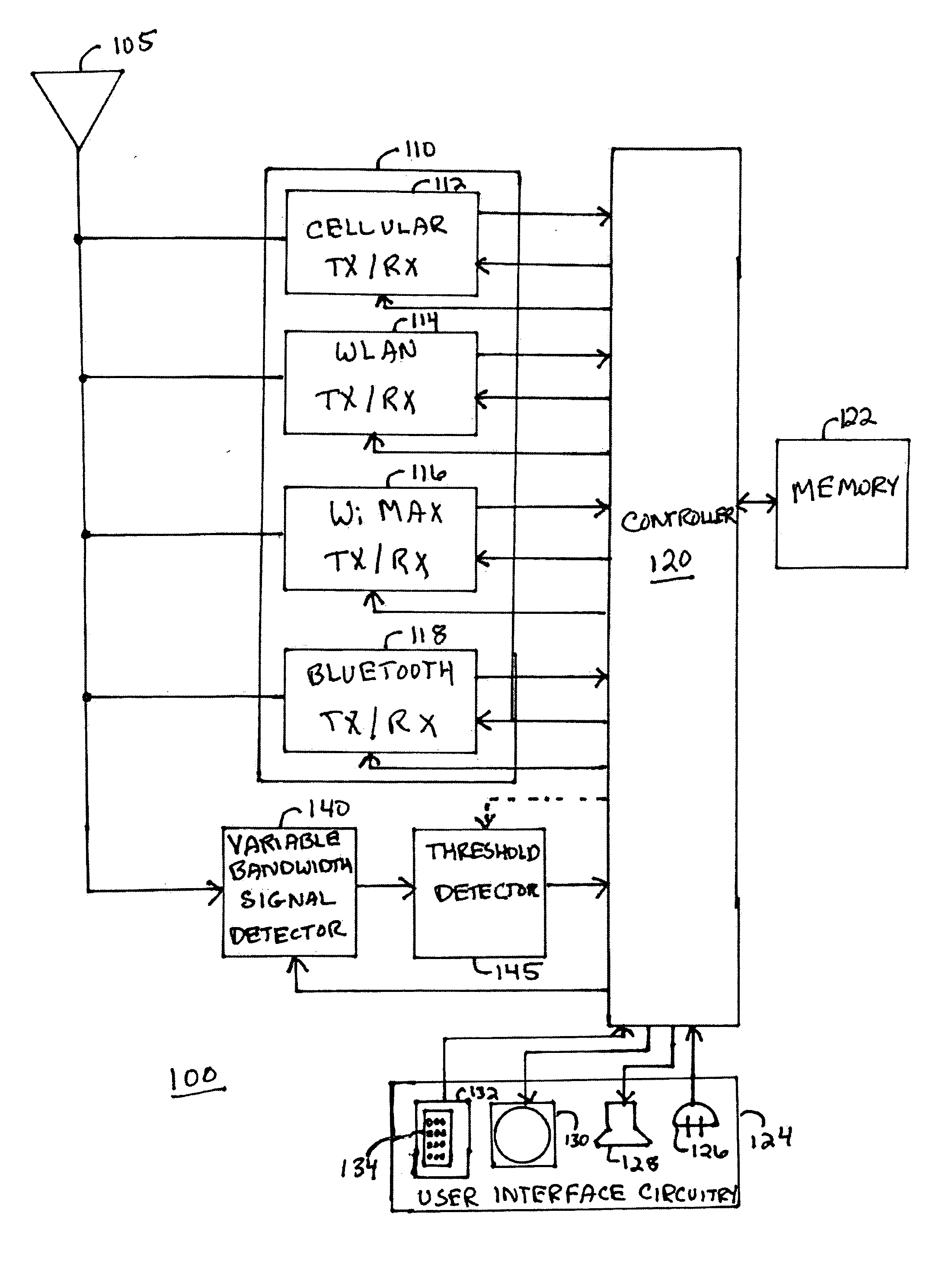
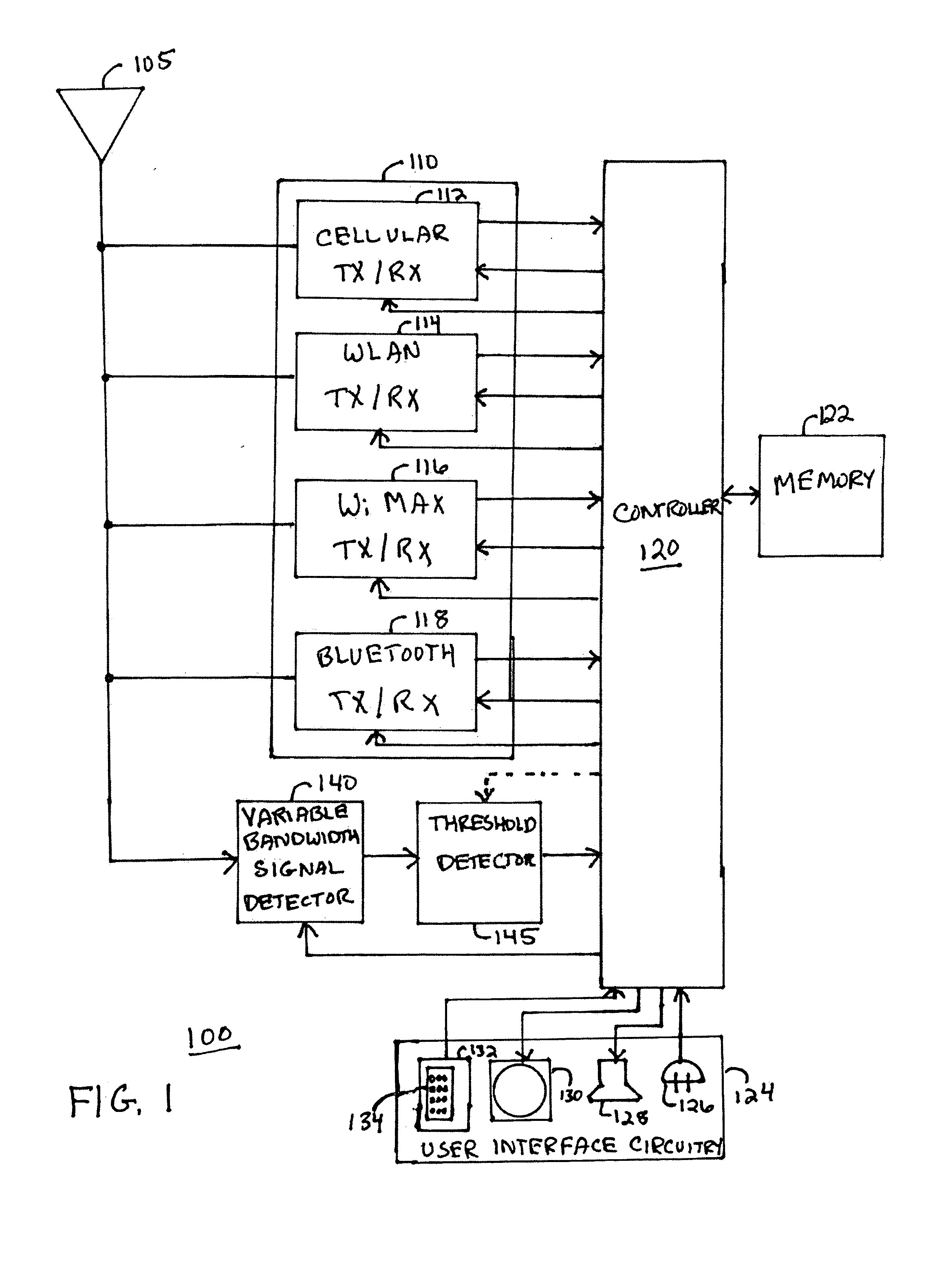
[0013]Referring to FIG. 1, a multi-mode radio frequency (RF) wireless communication device 100 in accordance with the present invention is shown. The multi-mode wireless communication device 100 can operate in a plurality of networks, each of the plurality of networks being defined by a radio access technology such as cellular telephone signaling technologies (e.g., CDMA, GSM), alternative network technologies (e.g., WiMAX) or short range network technologies (e.g., WLAN, Bluetooth). The wireless communication device 100 includes an antenna system 105 coupled to transceiver circuitry 110 for communicating in the plurality of networks. The transceiver circuitry 110 includes a plurality of transceivers 112, 114, 116, 118 for receiving signals from the antenna system 105 and demodulating and decoding the RF signals in accordance with the radio access technologies to recover information therefrom, as well as encoding and modulating information in accordance with the radio access technol...
second embodiment
[0028]In accordance with the present invention, the threshold detector 502 is implemented in the controller 120 such that the digital signal from the A / D 206 of the Bluetooth transceiver 118 is supplied to the threshold detector 502 portion of the controller 120 during network signal detection and the threshold detector 502 portion of the controller 120 determines whether a signal is present within the detection bandwidth having a signal strength greater than the predetermined signal strength.
third embodiment
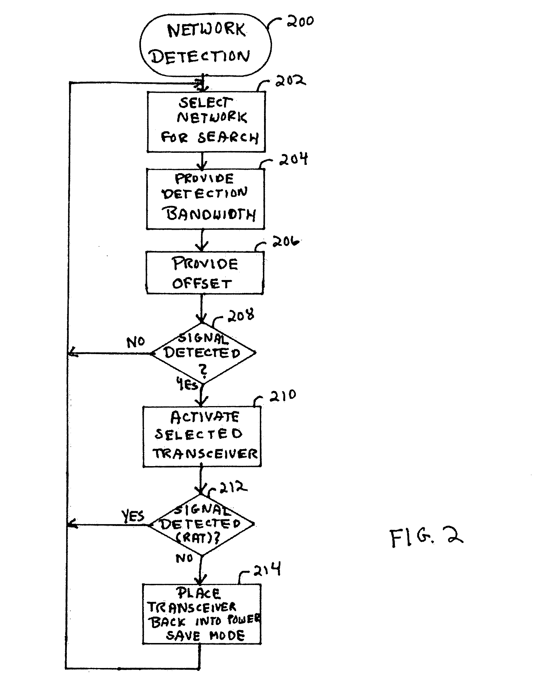
[0029]Referring to FIG. 6, an additional operation 600 can be performed by the controller 120 before performing the network detection operation 200 to mitigate cellular transmitter interference therewith in accordance with the present invention. Initially, the controller 120 determines whether the transmitter portion of the cellular transceiver 112 is active 602. If the cellular transmitter is not active 602, the network detection operation 200 is performed 604.
[0030]If, however, the cellular transmitter is active 602, the controller determines whether the cellular transmitter frequency will not affect the network detection operation 606. For example, if the cellular transmitter is operating at frequencies too far from the detection bandwidth to significantly affect signal detection, the network detection operation 200 will not be affected 606. If the controller 120 determines that the cellular transmitter frequency will affect the network detection operation 606, the network detect...
PUM
 Abstract
Description
Claims
Application Information