Storage Bin

a technology for storage bins and bins, applied in the field of storage bins, can solve the problems of laborious construction of field bins, inability to easily transport, and relatively heavy weight of field bins of this type, and achieve the effects of easy deterioration of field bins

Inactive Publication Date: 2008-02-07
AUSTRALIAN KEG
View PDF11 Cites 105 Cited by
  • Summary
  • Abstract
  • Description
  • Claims
  • Application Information

AI Technical Summary

Benefits of technology

[0020] The pads may be arranged in an array defining spaces for receiving lifting elements such as lifting forks of a forklift, a pallet carrier or an agricultural machine equipped with lifting forks. This is particularly advantageous as it allows the storage bin to be transported readily.

Problems solved by technology

Field bins of this type can be relatively heavy and are not readily transportable from one location to another on a farm.
Further, the field bins can be laborious to construct as it is necessary to construct the frame structure and thereafter assemble the metal sheeting in order to provide the storage bin.
Still further, the field bins are susceptible to deterioration through rusting, owing to their metal construction.

Method used


Image

  • Storage Bin
  • Storage Bin
  • Storage Bin

Examples


Embodiment Construction

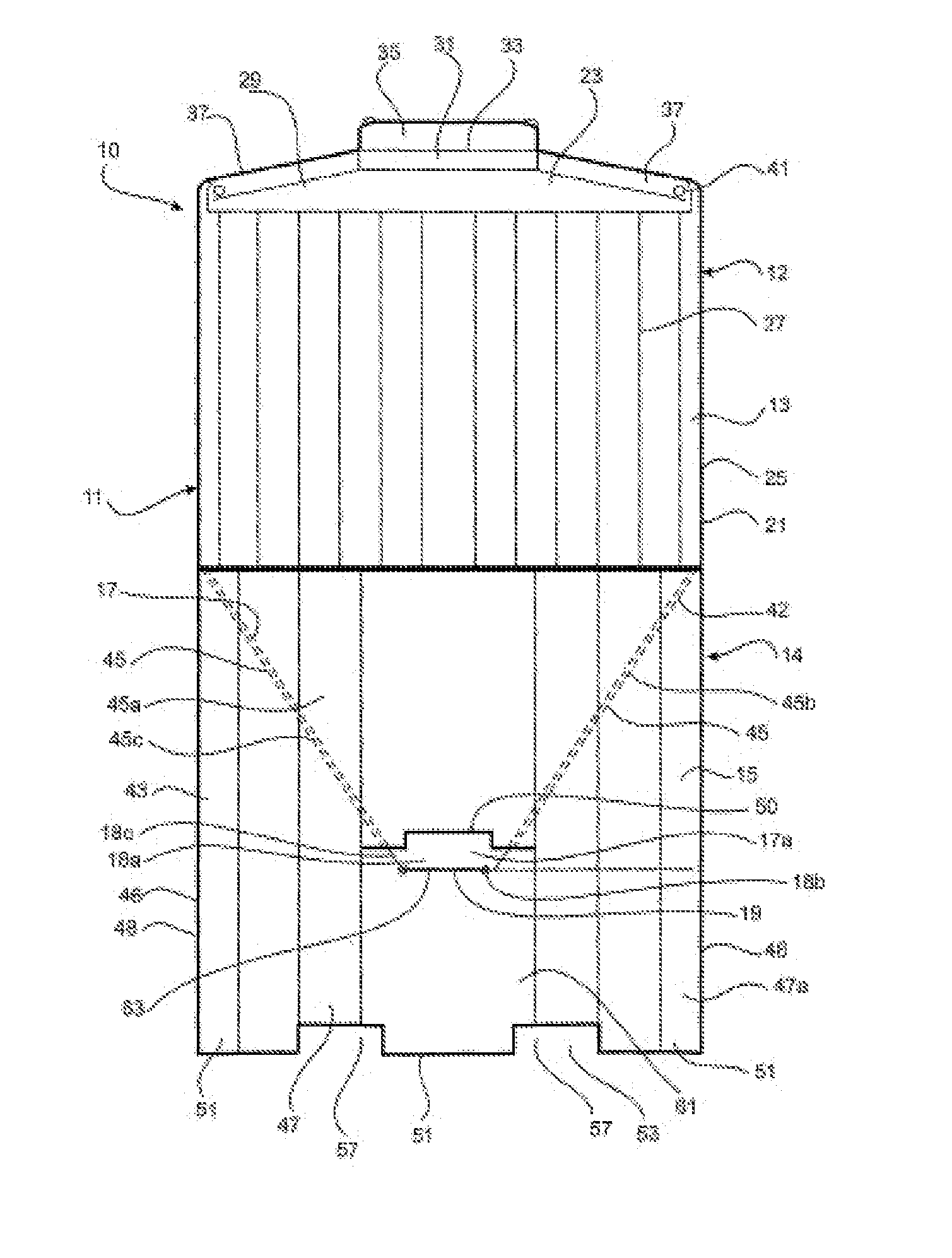
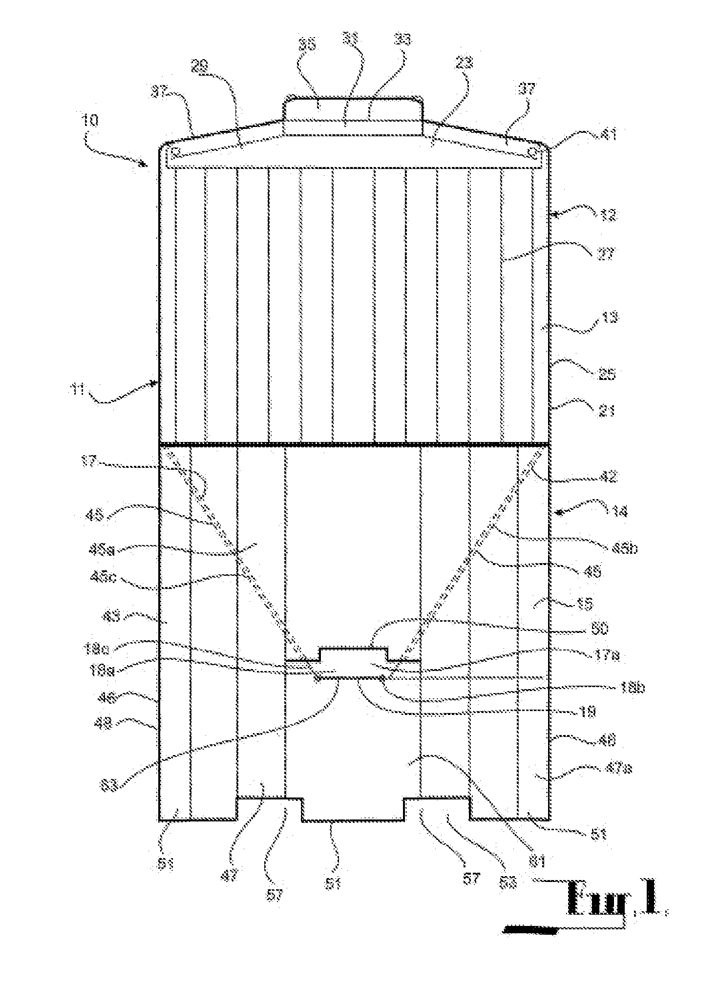
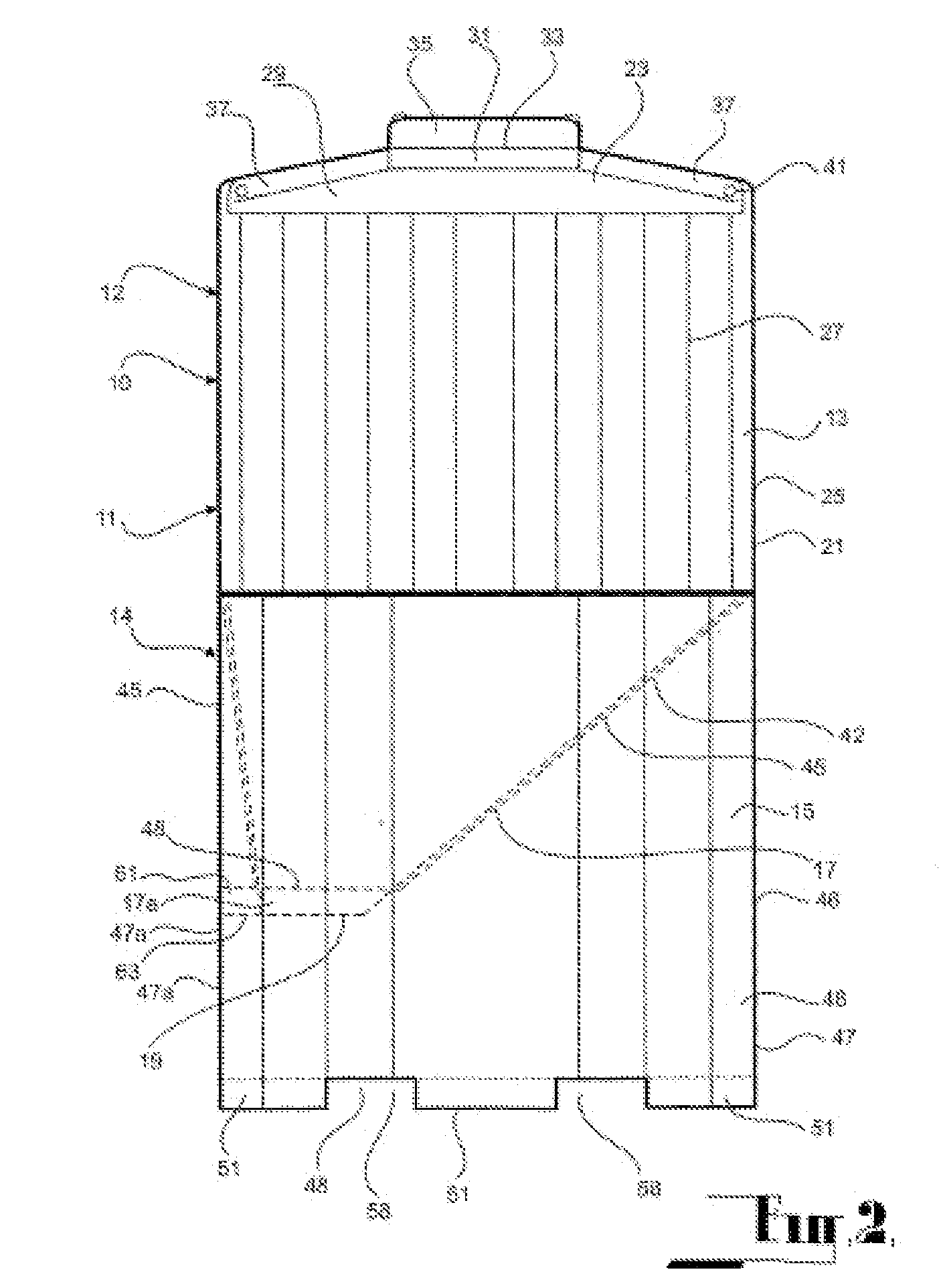
[0036] The embodiments shown in the drawings are each directed to a storage bin in the form of a field bin typically for use on farms for storage of grain such as wheat.

[0037] Referring to FIGS. 1 to 6, the field bin 10 according to the first embodiment comprises a body 11 formed of plastics material such as linear low-density polyethylene. The body 11 is formed in two sections, being an upper section 12 and a lower section 14. The upper section 12 defines a storage chamber 13, and the lower section 14 defines a base 15 below the storage chamber for supporting the storage chamber 13 in an elevated condition with respect to the ground (or any other surface on which the storage bin is located). The storage chamber 13 and the base 15 on which it is supported are each rectangular in plan, as best seen in FIGS. 3 and 4.

[0038] The storage chamber 13 comprises a bottom 17 sloping downwardly towards an outlet 19, a side 21 and a top 23 cooperating to define a storage zone 24 within the st...


PUM


Abstract

A storage bin comprising a body formed of plastic material. The body is formed in two sections, an upper section defining a storage chamber and a lower section defining a base below the storage chamber for resting on the ground. The storage chamber comprises a side and a bottom sloping downwardly towards the outlet. The base comprises a cradle section configured to receive and support the sloping bottom of the storage chamber. The base an opening extending between the cradle section and a recess in the base, section whereby the lowermost end of the sloping bottom of the storage chamber extends into the recess through the opening. The recess opens onto the exterior of the base whereby the outlet can be accessed through the recess.

Description

CROSS REFERENCE TO RELATED APPLICATIONS [0001] This utility patent application claims priority to Australian patent application 2004905114 filed on Sep. 8, 2004, and to international patent application PCT / AU2005 / 001368 filed on Sep. 8, 2005.FIELD OF THE INVENTION [0002] This invention relates to a storage bin. The invention has been devised particularly, although not necessarily solely, as a field bin for storage of grain, such as wheat. BACKGROUND ART [0003] Field bins are commonly used on farms for storage of wheat. Known field bins typically comprise a metal frame structure and sheet metal assembled on the frame structure to provide a storage bin, with the frame structure supporting the storage bin in an elevated condition above the ground so as to provide access to an outlet on the underside of the bin through which stored grain can be discharged. [0004] Field bins of this type can be relatively heavy and are not readily transportable from one location to another on a farm. [00...

Claims


Application Information

Patent Timeline
Patent Type & Authority Applications(United States)
IPC IPC(8): B65D88/26B65D6/34
CPCB65D88/26B65D90/12B65D88/30
Inventor CULLETON, RODNEY N.
Owner AUSTRALIAN KEG
Why Eureka
Try Eureka