Shoe Heel Cup and Shoe Equipped with One Such Heel Cup

a technology of heel cup and shoe, which is applied in the field of multi-purpose sports shoes, walking shoes, orthopedic shoes, etc., can solve the problems of lack of comfort or protection, risk of rapid deterioration of shoes, and insufficient adaptation of traditional shoes to physiological movements, so as to improve comfort and safety of shoes, without compromising comfort

Inactive Publication Date: 2008-02-14
RHENTER JEAN LUC
View PDF8 Cites 21 Cited by
  • Summary
  • Abstract
  • Description
  • Claims
  • Application Information

AI Technical Summary

Benefits of technology

[0015]The problem addressed by the present invention is improving both the comfort and the safety of shoes, thereby avoiding the drawbacks of traditional shoes, so as to support the natural foot and ankle joints without compromising comfort.
[0016]Another object of the invention is to propose a particularly simple and inexpensive structure that enables simultaneous improvement of protection and comfort.
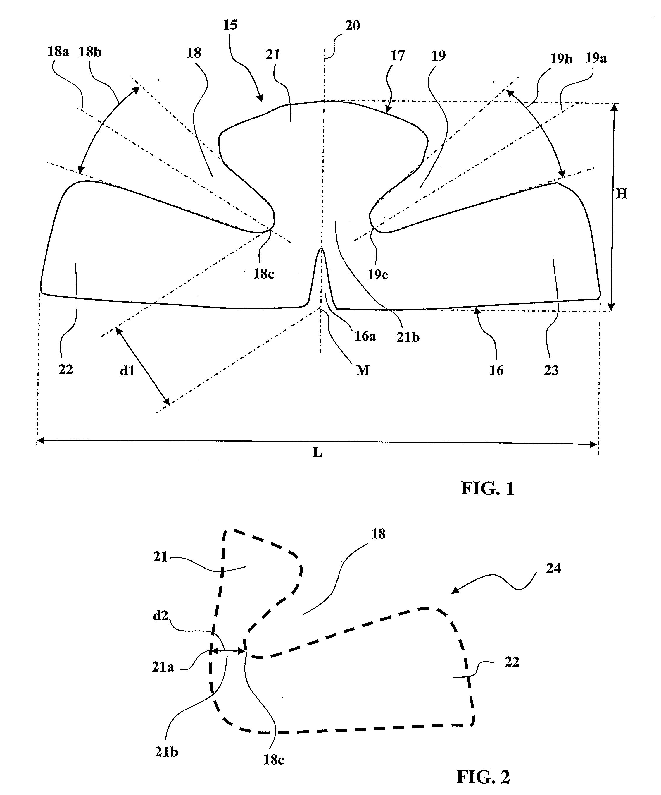
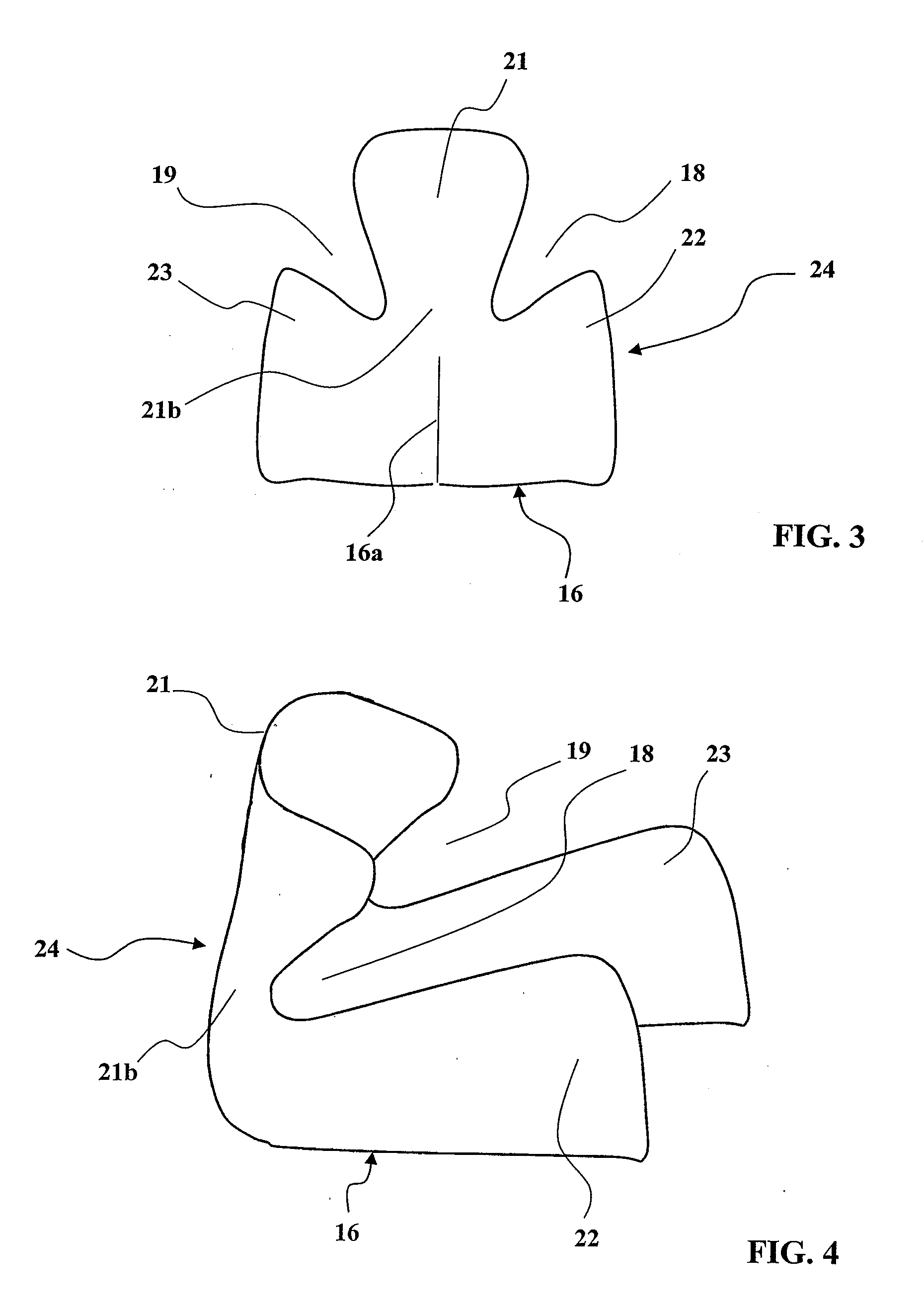
[0020]The heel cup constructed in this way is a particularly simple and inexpensive item and its use in a shoe considerably improves the trade-off achieved between the necessities of protecting the heel and the joints and the necessities of comfort resulting from a great freedom of movement of the joints.
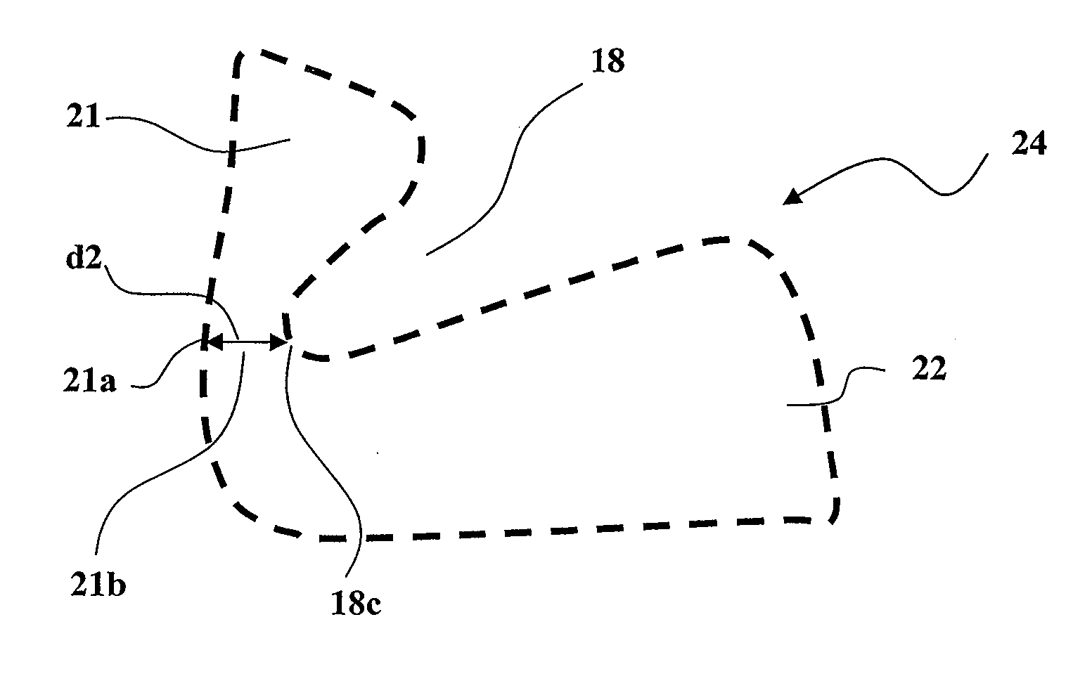
[0022]The aperture angle of the V-shaped lateral cutouts may advantageously be greater than the angle of the sub-astragalus cone, which effectively frees the movements of inversion and eversion of the ankle.
[0023]Cutouts having greater or lesser depths could be envisaged. The depth of the lateral cutouts is preferably such that, when the heel cup is in place in the shoe, the bottom of the lateral cutouts is slightly to the rear of the sub-astragalus joint. This achieves a good trade-off between the comfort resulting from the presence of the lateral cutouts and the protection resulting from the posterior portion of the cup being free of cutouts and absorbing mechanical forces.
[0033]At least in the area of the lateral cutouts, the upper and / or the vamp may advantageously constitute an elastic deformation area of lower stiffness.

Problems solved by technology

It has become apparent in this way that traditional shoes are not sufficiently well adapted to the physiological movements of the foot and ankle joints, and that this is what explains either the lack of comfort or the lack of protection, or even the risk of rapid deterioration of the shoe.

Method used


Image

  • Shoe Heel Cup and Shoe Equipped with One Such Heel Cup
  • Shoe Heel Cup and Shoe Equipped with One Such Heel Cup
  • Shoe Heel Cup and Shoe Equipped with One Such Heel Cup

Examples


Embodiment Construction

[0042]FIG. 5 is considered first, in order to outline the main structural components of a foot joint and the main movements of that joint.

[0043]The foot 1 is represented in a shoe consisting of a sole 2 and an exterior upper 3 represented in dashed lines.

[0044]The sole 2 of the shoe is resting on a horizontal plane P and the shoe extends longitudinally along a vertical plane perpendicular to the plane P, or plane of the figure.

[0045]Of the foot 1, shown inside the shoe, there are seen the calcaneum 4, the astragalus 5, the cuboid 6, the scaphoid 7 and the cuneiforms 8 that are followed by the metatarsals and the phalanges, not shown.

[0046]The calcaneo-pedal block, consisting of the calcaneum 4, the cuboid 6, the scaphoid 7 and the cuneiforms 8, forms the lower structure of the foot, which rests on the sole 2 of the shoe.

[0047]This calcaneo-pedal block is articulated to the bottom of the leg, indicated by the lower end of the tibia 9, by a joint with two successive stages, namely a t...


PUM

PropertyMeasurementUnit
heightaaaaaaaaaa
lengthaaaaaaaaaa
aperture angleaaaaaaaaaa

Abstract

A heel cup can be inserted into a shoe in order to define a posterior upward projection and lateral wings which surround the posterior and lateral faces of the calcaneum and which, through lateral notches, define a preferential deformation zone at, and in the direction of, the subtalar cone of the tibiotarsal joint. Moreover, a sufficiently-rigid connecting zone connects the posterior upward projection and the lateral wings, thus providing the shoe with good stability while enabling inversion and eversion foot movements. In this way, comfort is increased considerably, while the risk of articular injuries is reduced since the subtalar articulation is contained correctly upon reaching the limit thereof.

Description

TECHNICAL FIELD OF THE INVENTION[0001]The present invention concerns footwear and more particularly, although not exclusively, multipurpose sports shoes, walking shoes, orthopedic shoes.[0002]Whatever the application concerned, shoes must assume different functions and in particular a function of mechanical protection of the sensitive portions of the foot against impact and a function of holding or supporting the foot and ankle joints.[0003]To fulfill their function of impact protection, shoes must in particular protect the heel and the area of attachment of the Achilles tendon.[0004]To fulfill their function of holding or supporting the joints, shoes must in particular limit the forces on the ankle and foot joints when they are close to their maximum amplitude of movement.[0005]However, a shoe must simultaneously allow free functioning of the ankle and foot joints for the various movements of walking, running, jumping, turning.[0006]Clearly there is a contradiction between the nece...

Claims


Application Information

Patent Timeline
Patent Type & Authority Applications(United States)
IPC IPC(8): A43B7/20A43B7/14A43B23/17A61F5/01
CPCA43B3/0068A43B23/17A43B7/20
Inventor RHENTER, JEAN-LUC
Owner RHENTER JEAN LUC
Why Eureka
Try Eureka