Automated molding cut-off saw and method

a technology of automatic molding and cutting-off saw, which is applied in the direction of metal sawing equipment, metal-working accessories, metal-working tools, etc., can solve the problems of no printing or marking capability to designate, the method is extremely time-consuming, and the patent does not disclose the use of the blades to cut angular miter or compound angl

Inactive Publication Date: 2008-02-14
MEKKELSEN THOMAS C JR
View PDF16 Cites 14 Cited by
  • Summary
  • Abstract
  • Description
  • Claims
  • Application Information

AI Technical Summary

Benefits of technology

[0008]It is an object of the automatic cut-off saw to provide an automatic saw for use in measuring and cutting elongated material such as floor wall and crown molding, wood, plastic or metal. The automated saw utilizes a measurement and data storage mechanism such as a hand held phone or PDA and the dimensions of a room are measured and entered into the device where they are communicated to the cutting saw. The input can have a voice entry of the data as measurements are taken, and further provide an audible announcing of the measurement to confirm the entered data. In the installation of the moldings on multiple “similar” rooms such as hotel rooms, the data storage device includes learning and verify mode where it prompts the user around a similar room to determine variations based upon wall inconsistencies. The data storage device further prompts the user for angles and variables where the dimensions and end cuts can be visually or audibly verified. The communication from the measurement / data storage device is with a wired or wireless link where the data is transferred to the saw and or a computer.

Problems solved by technology

This method is extremely time consuming.
While this patent discloses two saw blades that cut opposite ends of a piece of molding the distance between the cutting saw blades is manually adjusted and the patent does not disclose using the blades to cut angular miter or compound angles.
In addition there is no printing or marking capability to designate where the material is to be installed.
The patent does not disclose using the blades to cut angular miter or compound angles
This patent also does not allow for dynamic entry of variable length boards where the machine automatically indexes to accommodate the various lengths.
It also does not include a printer / marker or allow for compound miter cutting angles.

Method used


Image

  • Automated molding cut-off saw and method
  • Automated molding cut-off saw and method
  • Automated molding cut-off saw and method

Examples


Embodiment Construction

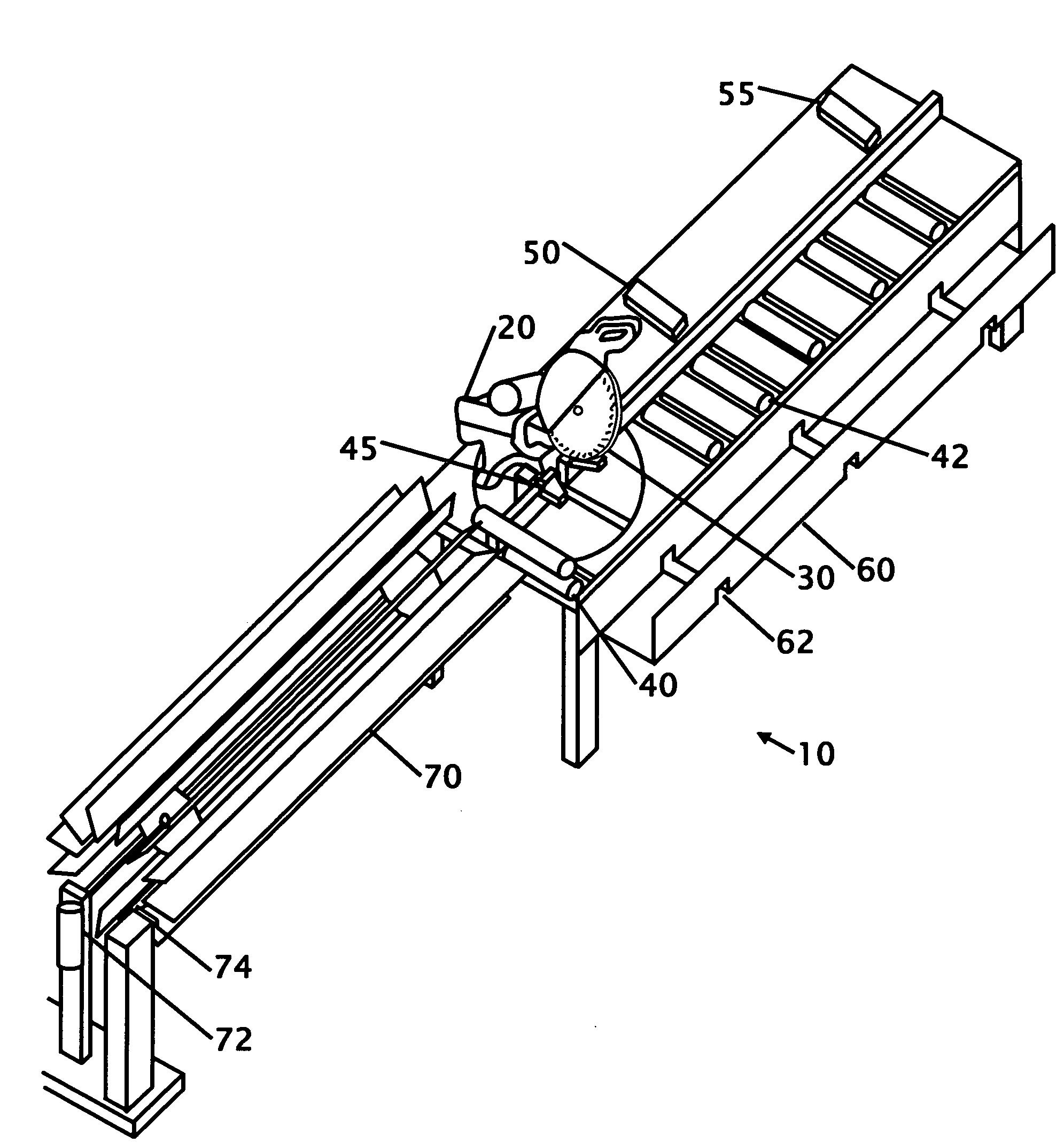
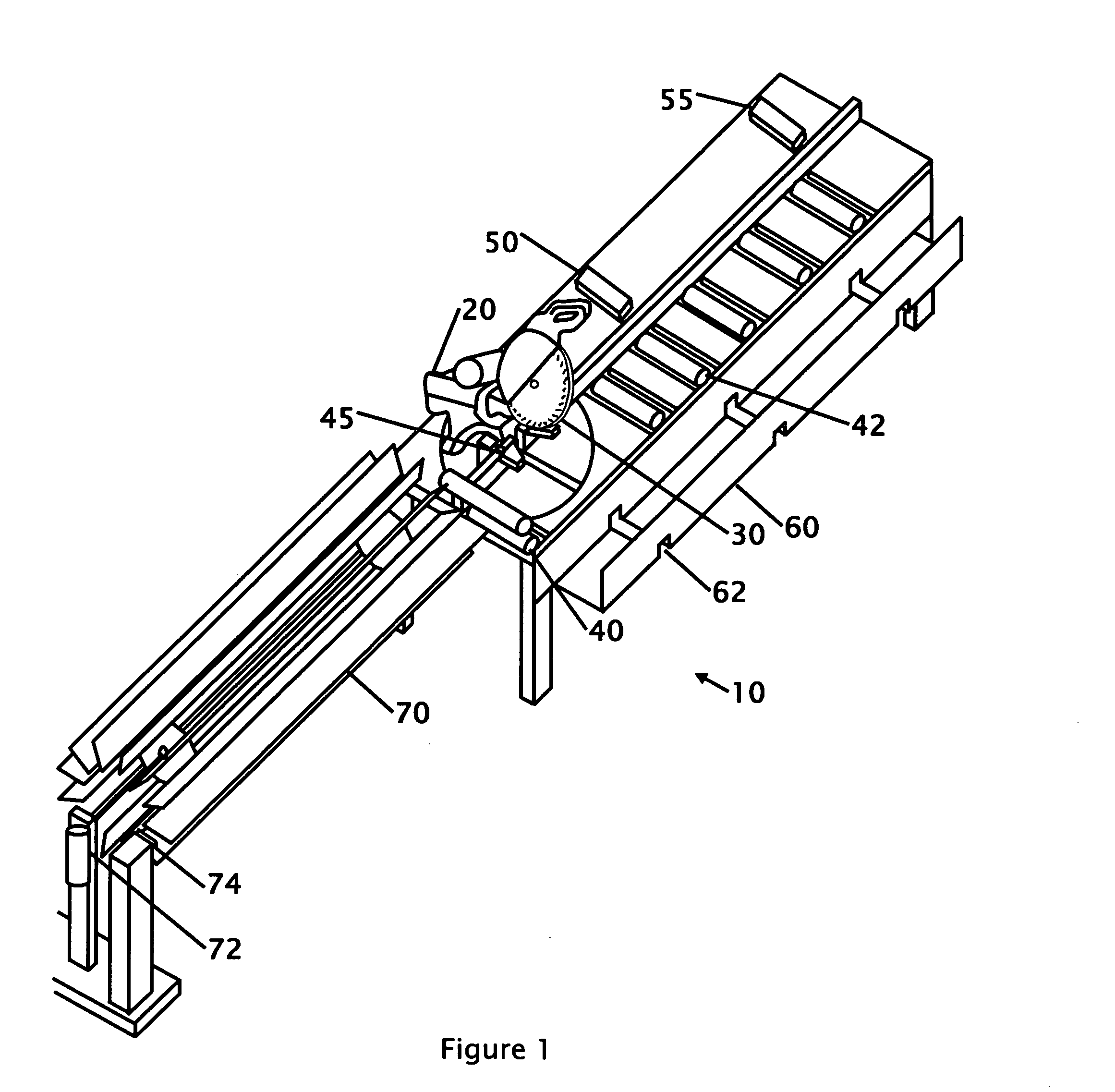
[0024]FIG. 1 shows an isometric view of the automated molding cut-off saw 10 according to a preferred embodiment. This view shows the overall molding cutting machine with its various components. A detailed view showing the elements around the saw is found in FIG. 5. The saw 20 is a combination type saw where the angle and tilt of the blade is adjustable to match the requirements for making miter cuts to floor, wall and crown molding. It is contemplated that the saw and feeding mechanism is powered by one or multiple power sources including but not limited to wall supplied AC power, air and batteries. In this figure a rotary material dispensing apparatus 70 is shown for feeding material into the cutting portion or blade of the machine. While in this description, moldings are predominantly indicated, it is contemplated that the automatic saw in use with the data recording and transfer system is equally suited for use with metal, wood, plastic and other elongated materials.

[0025]In thi...


PUM

PropertyMeasurementUnit
angleaaaaaaaaaa
degree angleaaaaaaaaaa
lengthaaaaaaaaaa

Abstract

Improvements in a cut-off miter saw for floor, wall, crown molding, wood, plastic, metal and the like are disclosed that includes an automated or manually fed cut-off saw where measurements are dynamically entered into a wireless communications device. The measurements are organized and sent to a cut-off saw where the material is cut with a first angle, indexed and cut at a second angle. The parts are further marked or organized and routed to the installer. This offers a tremendous improvement and reduction in the amount of time presently required to perform these operations in a serial order. It is particularly useful in measuring, cutting and nailing floor molding in houses, or other buildings where each room has slightly different dimensions and each length is custom fit.

Description

FIELD OF THE INVENTION[0001]This invention relates to improvements a molding, wood, plastic or metal cut-off miter saw and method of use. More particularly, the present automatic saw includes an automated or manually fed cut-off saw for floor, wall crown molding wood, plastic, metal or the like where measurements are dynamically entered into a wireless communications device where the data is sent to the cut-off saw and the material is cut with a first angle, indexed and cut at a second angle. The parts are further marked or organized and routed to be installed.BACKGROUND OF THE INVENTION[0002]When a room is finished the area around the outside floor is usually finished with a molding. Moldings are also often placed on the ceiling as crown molding or on the wall as chair railing. Presently most floor wall and crown molding are cut in a serial manner where first the dimensions of a room are measured and written down. The measurements are then taken to a cutting saw or station where th...

Claims


Application Information

Patent Timeline
Patent Type & Authority Applications(United States)
IPC IPC(8): B26D5/20
CPCB23D59/008B23D59/001Y10T83/18Y10T83/849
Inventor MEKKELSEN, THOMAS C.ROUSSEAU, HECTOR
Owner MEKKELSEN THOMAS C JR
Why Eureka
Try Eureka