Apparatus for and method of discharging tape

Inactive Publication Date: 2008-02-14
SAMSUNG TECHWIN CO LTD
View PDF13 Cites 11 Cited by
  • Summary
  • Abstract
  • Description
  • Claims
  • Application Information

AI Technical Summary

Benefits of technology

[0019]The present invention provides an apparatus for

Problems solved by technology

However, trays are not suitable to supply small components.
When very small components such as semiconductor chips are mounted on a printed circuit board, the components may be lost or damaged while being transported.
Further, it is difficult to pick up the small components one by one.
Furthermore, the small components are easily damaged by environmental agents such as dust.
As a result, a pick-up point can be deviated, and thus the operation of the tape feeder may be affected.
However, such a conventional tape discharging apparatus has a disadvantage in that the top cover

Method used


Image

  • Apparatus for and method of discharging tape
  • Apparatus for and method of discharging tape
  • Apparatus for and method of discharging tape

Examples


Example

[0048]The present invention will now be described more fully with reference to the accompanying drawings, in which exemplary embodiments of the invention are shown.

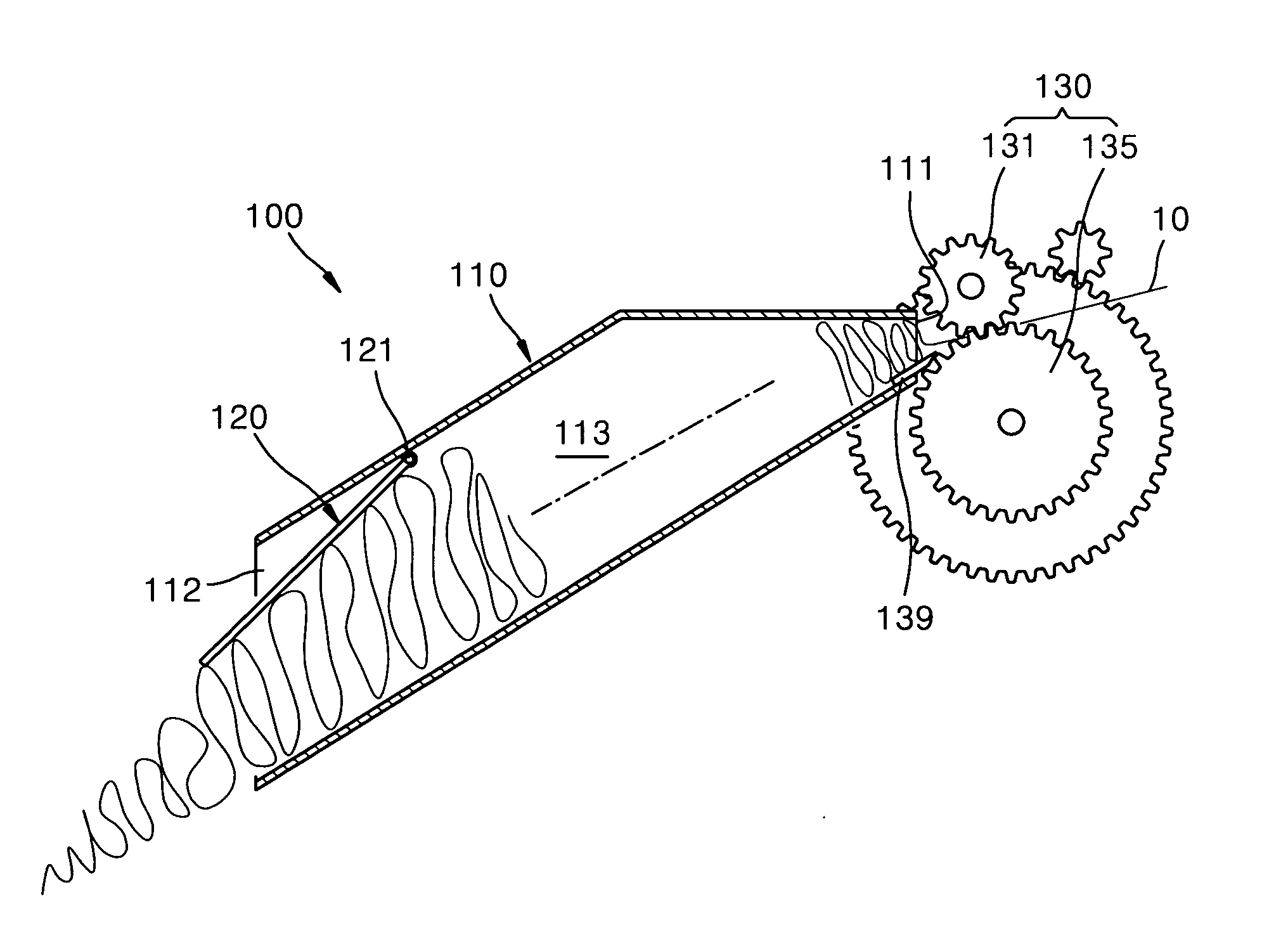
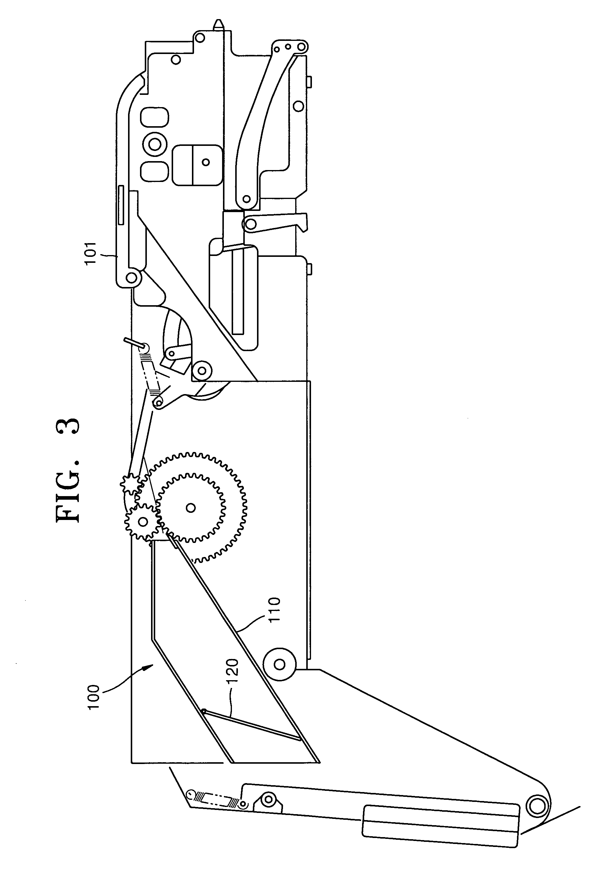
[0049]FIG. 3 is a partial side view illustrating a tape feeder with a tape discharging apparatus 100 according to an embodiment of the present invention, and FIG. 4 is a perspective view illustrating the tape discharging apparatus 100 according to an embodiment of the present invention.

[0050]The tape discharging apparatus 100 is used in the tape feeder of a component mounter. When assembled, the tape feeder is attached to one side of the component mounter. The tape feeder includes a tape separating unit 101 and the tape discharging apparatus 100. The tape separating unit 101 separates a top cover tape from a top surface of a carrier tape on which chips are attached. The separated top cover tape is fed to the tape discharging apparatus 100 where the tape is discharged into a tape collector 110.

[0051]The tape discharging ap...


PUM


Abstract

An apparatus for and method of discharging a cover tape. The apparatus includes a tape collector including an inlet through which a top cover tape is introduced into the tape collector, an outlet through which the top cover tape is discharged from the tape collector, and a passage formed inside the tape collector to receive the top cover tape from the inlet and guide the top cover tape to the outlet; and a discharge guide rotatably installed inside the tape collector, the discharge guide being rotated to open the outlet by a pushing force exerted by the top cover tape fully filled in the passage, the discharge guide returning to an original position to close the outlet after the top cover tape filled in the tape collector is discharged through the outlet.

Description

CROSS-REFERENCE TO RELATED PATENT APPLICATION[0001]This application claims the benefit of Korean Patent Application No. 10-2006-0075308, filed on Aug. 9, 2006, in the Korean Intellectual Property Office, the disclosure of which is incorporated herein in its entirety by reference.BACKGROUND OF THE INVENTION[0002]1. Field of the Invention[0003]The present invention relates to an apparatus for discharging a tape, and more particularly, to an apparatus for receiving and discharging a top cover tape in a tape feeder.[0004]2. Description of the Related Art[0005]A tape feeder is used in a component mounter such as a chip mounter to supply components. A chip mounter is a device that mounts components such as semiconductor chips on a printed circuit board at desired positions. Various components are supplied to the chip mounter in various ways, and the chip mounter mounts the components on a printed circuit board using a suction nozzle or the like.[0006]Components are supplied to the chip mo...

Claims


Application Information

Patent Timeline
IPC IPC(8): B65H20/02
CPCB65H20/30B65H2701/37B65H2408/212H05K13/02
Inventor KIM, YOUNG-IL
Owner SAMSUNG TECHWIN CO LTD
Why Eureka
Try Eureka