
Adjustable Seat Cushion Bolster Mechanism

Inactive Publication Date: 2008-02-14
INTIER AUTOMOTIVE INC
View PDF14 Cites 39 Cited by
  • Summary
  • Abstract
  • Description
  • Claims
  • Application Information

AI Technical Summary

Benefits of technology

[0005] According to one aspect of the invention, a seat frame assembly is provided for compactly folding a motor vehicle seat. The seat frame assembly includes at least one side frame member. An actuator is operatively coupled to the side frame member. An elongated control arm includes a first end pivotally coupled to the side frame member and an opposing distal end. A control link has one end pivotally coupled to the side frame member and an opposing end operatively coupled to the distal end of control arm. A seat cushion linkage assembly is coupled between one of the control arm and the control link and the actuator for moving the control arm and control link between a stowed position generally parallel and adjacent to the side frame member and a support position spaced from the side frame member in response to actuation of the actuator.
[0006] According to another aspect of the invention, a motor vehicle seat includes a seat cushion having at least one side frame member. A first control arm is pivotally coupled to the side frame member of the seat cushion for movement between a support position and a stowed position. A seat back is pivotally coupled to the seat cushion and has at least one side frame member. A second control arm is pivotally coupled to the side frame member of the seat back for movement between a support position and a stowed position. An actuator is operably coupled to the first control arm for moving the first control arm between the support and stowed positions. A cable assembly is operably connected between the first control arm and the second control arm for urging the second control arm between the support and stowed positions as the actuator moves the first control arm between the respective support and stowed positions to selectively allow compact folding of the seat back against the seat cushion.

Problems solved by technology

The side bolsters present, however, a problem during folding of the seat back into its stowed position.

Method used


Image

  • Adjustable Seat Cushion Bolster Mechanism
  • Adjustable Seat Cushion Bolster Mechanism
  • Adjustable Seat Cushion Bolster Mechanism

Examples


Embodiment Construction

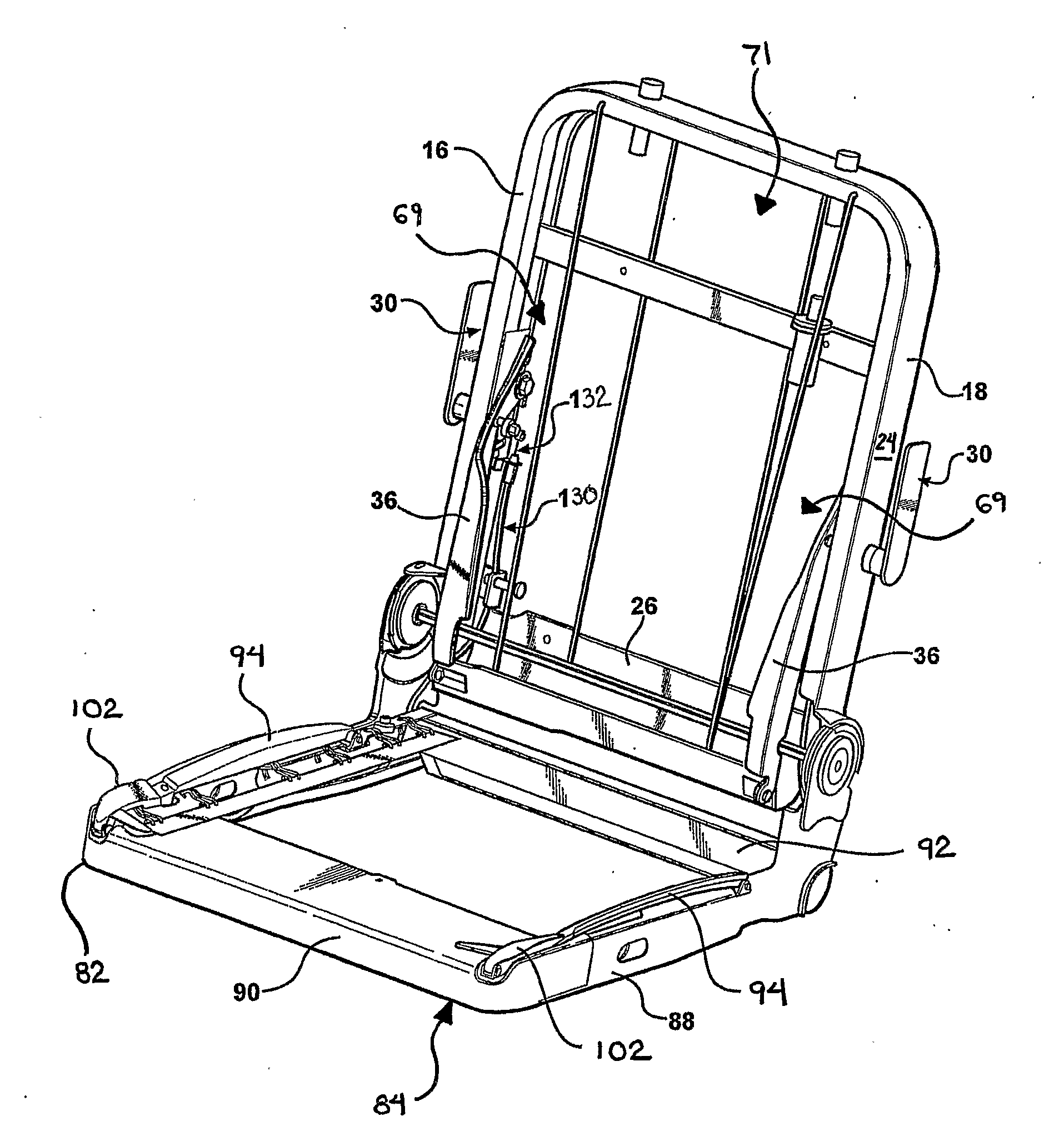
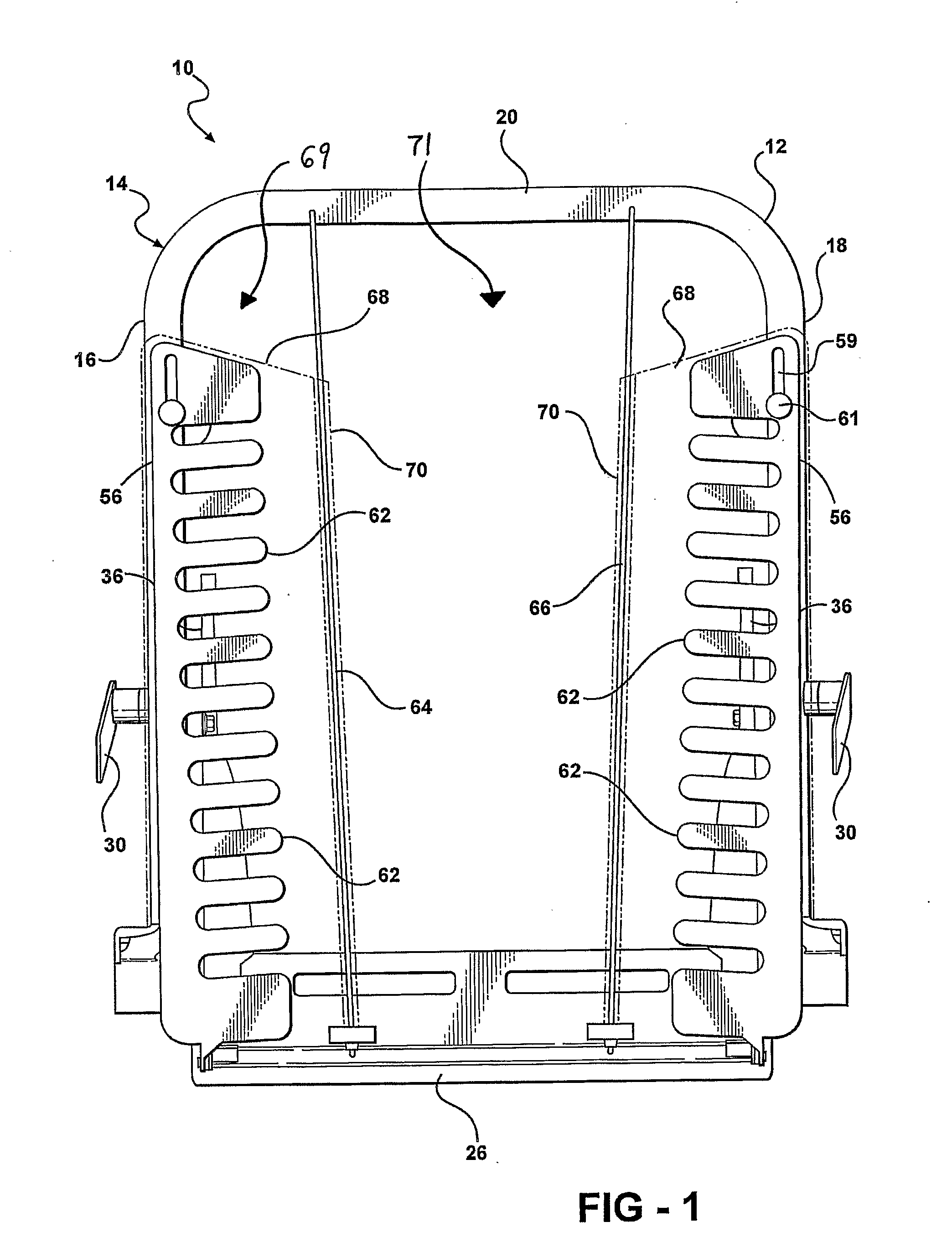
[0023] Referring to FIG. 1, according to a first embodiment of the invention, a seat, generally shown at 10, includes a seat back 12 having a seat frame assembly, generally indicated at 14, for supporting a foam pad (not shown) encased in a trim cover (not shown). It will be appreciated that although the seat frame assembly 14 for the seat back 12 is shown, the same general construction of the seat frame assembly 14 may be utilized for a seat cushion (not shown).

[0024] The seat frame assembly 14 includes side frame members 16, 18 and an upper cross member 20 extending between the side frame members 16, 18. The side frame members 16, 18 are generally parallel and define a vertical plane therebetween. The seat frame assembly 14 also includes a lower cross member 26 extending between the side frame members 16, 18. The lower cross member 26 is spaced apart from and parallel to the upper cross member 20.

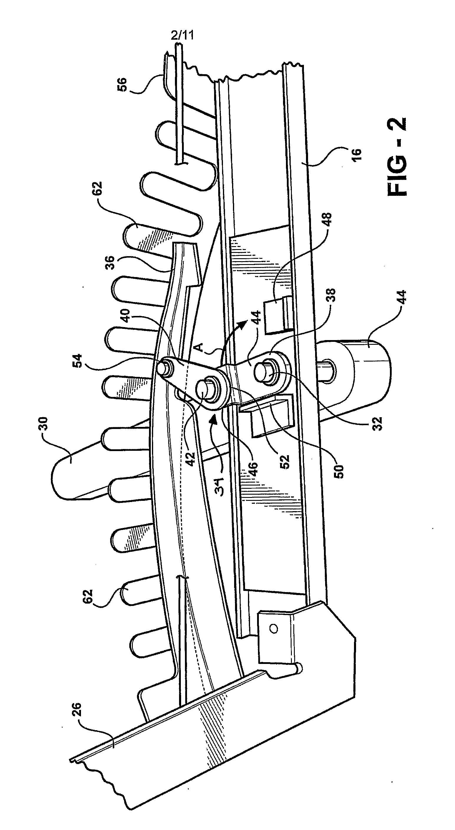
[0025] Referring to FIGS. 1 through 4, an actuator 30 is pivotally secured to each ...


PUM


Abstract

A seat frame assembly is provided for compactly folding a motor vehicle seat. The seat frame assembly includes at least one side frame member. An actuator is operatively coupled to the side frame member. An elongated control arm includes a first end pivotally coupled to the side frame member and an opposite distal end. A control link includes one end pivotally coupled to the side frame member and an opposing end operatively coupled to the distal end of the control arm. A seat cushion linkage assembly is operably coupled between one of the control arm and control link and the actuator for moving each of the control arm and control link between a stowed position generally parallel with and adjacent to the side frame member and a support position spaced from the side frame member in response to actuation of the actuator.

Description

FIELD OF THE INVENTION [0001] This invention relates to a seat frame assembly for a motor vehicle seat. More particularly, the invention relates to a seat frame assembly including adjustable side bolsters that allow for compact folding of a motor vehicle seat. DESCRIPTION OF RELATED ART [0002] A motor vehicle includes one or more seat assemblies for supporting occupants within a passenger compartment. The seat assembly typically includes a seat cushion and a seat back pivotally secured to the seat cushion. The seat back is generally movable between an upright seating position and a stowed position, in which the seat back is folded against the seat cushion. When the seat back is in its stowed position, additional storage space is created within the passenger compartment above the folded seat back. [0003] The seat cushion and the seat back each include side bolsters or side support structures for supporting a seat occupant. Such side bolsters are particularly useful in supporting the ...

Claims


Application Information

Patent Timeline
IPC IPC(8): A47C7/14B60N2/02B60N2/90
CPCB60N2/449B60N2/20
Inventor HOLDAMPF, CARL J.WICKHAM, ARNOLD JAMESWELCH, CHRISTOPHER SCOTT
Owner INTIER AUTOMOTIVE INC
Features
  • Generate Ideas
  • Intellectual Property
  • Life Sciences
  • Materials
  • Tech Scout
  • Unparalleled Data Quality
  • Higher Quality Content
  • 60% Fewer Hallucinations
Learn More