
Liquid injecting method and liquid container

Inactive Publication Date: 2008-02-14
SEIKO EPSON CORP
View PDF4 Cites 7 Cited by
  • Summary
  • Abstract
  • Description
  • Claims
  • Application Information

AI Technical Summary

Benefits of technology

[0013] An advantage of some aspects of the invention is to provide a method of injecting a liquid into a liquid container into which the liquid can be injected without damage to a primary function of the liquid container, and the liquid container. The advantage can be attained by at least one of the following aspects:

Problems solved by technology

Accordingly, when ink is exhausted, the disposal of the ink cartridge results in a waste of a useful resource and a big economical loss.
Accordingly, after the ink cartridge is manufactured, there are many cases where the same ink injecting step cannot be used.
Moreover, a configuration of the ink containing chamber or an air communicating path becomes complicated.
For this reason, if a container body is arranged carelessly, when ink is injected, a poor re-use may be caused.
For example, the ink may leak into portions other than the ink containing portion or an original function may be damaged due to bubbles mixed when the ink is injected.
For this reason, a re-use may be impossible.
In particular, when the bubbles floating in the injected ink are stuck to the surface of a sensor of the ink residual quantity detecting mechanism, the stuck bubbles may cause a change in residual vibration.
Accordingly, whether the ink is present or not are not accurately detected, and thus it may be erroneously detected that the liquid level of the ink falls.

Method used


Image

  • Liquid injecting method and liquid container
  • Liquid injecting method and liquid container
  • Liquid injecting method and liquid container

Examples


Embodiment Construction

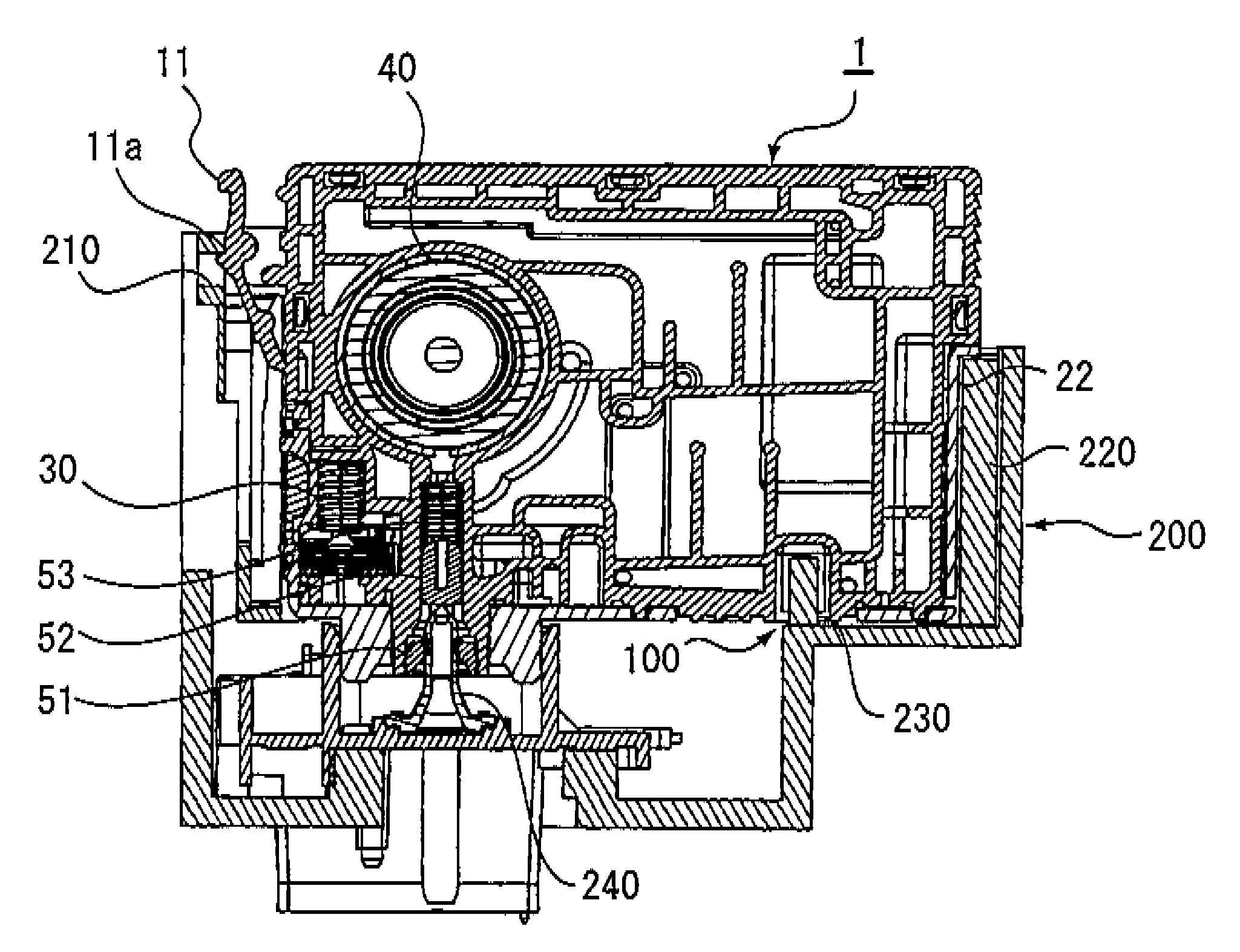
[0056] Hereinafter, a liquid injecting method and a liquid container according to an exemplary embodiment of the invention will be described in detail with reference to drawings. In the exemplary embodiment described below, as an exemplified liquid container, an ink cartridge mounted on an ink jet printing apparatus (printer), which is an example of a liquid ejecting apparatus, will be described.

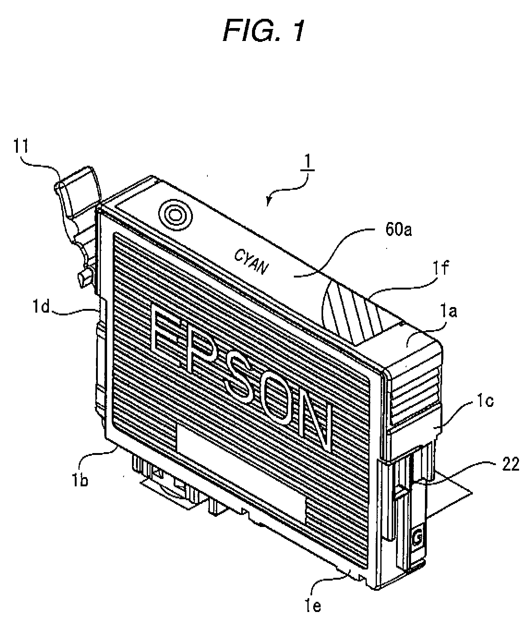
[0057]FIG. 1 is an exterior perspective view illustrating the ink cartridge which is an example of the liquid container according to an exemplary embodiment of the invention.

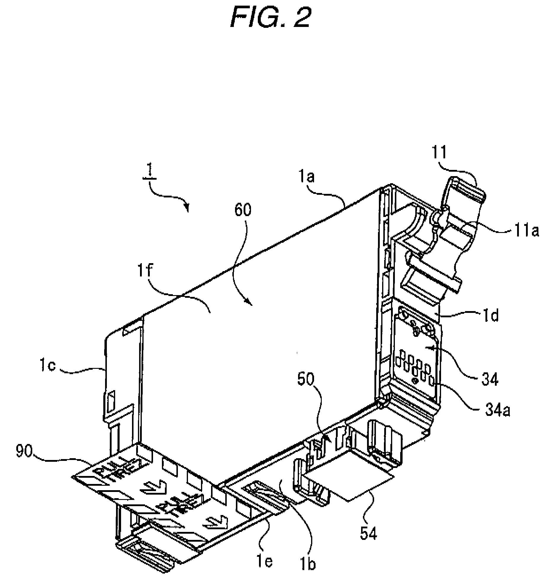
[0058]FIG. 2 is an exterior perspective view illustrating the ink cartridge according to the exemplary embodiment when viewed at an inverse angle in FIG. 1. FIG. 3 is an exploded perspective view illustrating the ink cartridge according to the exemplary embodiment. FIG. 4 is an exploded perspective view illustrating the ink cartridge according to the exemplary embodiment when viewed at an inverse angle in FIG. 3. FIG. ...


PUM


Abstract

A method of injecting a liquid into a liquid container detachably mounted on a liquid consuming device, the liquid container including; a liquid containing portion; a liquid supply portion connectable to the liquid consuming device; a liquid guide passage for guiding the liquid contained in the liquid containing portion to the liquid supply portion; an air communicating passage communicating the liquid containing portion with an air; a first inner wall surface; and a second inner wall surface intersecting with the first inner wall surface, the first inner wall surface having a liquid containing portion outlet formed close to the second inner wall surface and allowing the liquid containing portion to communicate with the liquid guide passage, the method including: forming an injection port communicating with the liquid containing portion in the air communicating passage; injecting a predetermined amount of liquid through the injection port; and sealing the injection port after injecting the liquid.

Description

BACKGROUND [0001] 1. Technical Field [0002] The present invention relates to a method of injecting a liquid in a liquid container of an open-air type that is suitable for an ink cartridge detachable from, for example, an ink jet printer and the like, and the liquid container. [0003] 2. Related Art [0004] As an ink cartridge (liquid container) detachable from a liquid consuming device such as an ink jet printer, various kinds of open-air type ink cartridge are suggested. The open-air ink cartridge has, in a container body detachable from a printer, an ink containing portion (liquid containing portion) that contains ink, an ink supply portion (liquid supply portion) that is connected to a printing head (liquid ejecting portion), an ink guide path (liquid guide path) that guides the ink stored in the ink containing portion to the ink supply portion, and an air communicating path that introduces air into the ink containing portion from the outside with a consumption of the ink in the co...

Claims


Application Information

Patent Timeline
IPC IPC(8): B41J29/38B41J2/175
CPCB41J2/17506B41J2/17513B41J2/1752B41J2/17533B41J2/17536
Inventor SHINADA, SATOSHIMIYAJIMA, CHIAKIMATSUYAMA, MASAHIDESEKI, YUICHIKOIKE, HISASHIKATSUMURA, TAKAYOSHI
Owner SEIKO EPSON CORP
Learn More