
High resolution 2d/3d switchable display apparatus

a display apparatus and high-resolution technology, applied in the direction of electrical devices, instruments, optics, etc., can solve the problem of user being unable to view an accurate 3-d imag

Active Publication Date: 2008-02-14
SAMSUNG ELECTRONICS CO LTD
View PDF6 Cites 67 Cited by
  • Summary
  • Abstract
  • Description
  • Claims
  • Application Information

AI Technical Summary

Benefits of technology

[0012]In one aspect, the present invention relates to a high resolution 2D/3D switchable display apparatus including a display panel having display elements arranged in pixel units and configured to display an image, a lenticular lens array including a plurality of lenticular lenses arranged in a horizontal direction and dividing light emitted from the display panel to visual regions of left eye and right eye, and a spatial optical modulator including a plurality of cells configured to switch on or off in synchronization with a vertical scanning time of the display panel. Each of the plurality of cells is changed to a transparent or opaque state. The display panel sequentially displays an even field including even sequence data of a left eye image and a right eye image and an odd field including odd sequence data of an image for the left eye and an image for the right eye.
[0013]In another aspect, the present invention relates to a high resolution 2D/3D switc

Problems solved by technology

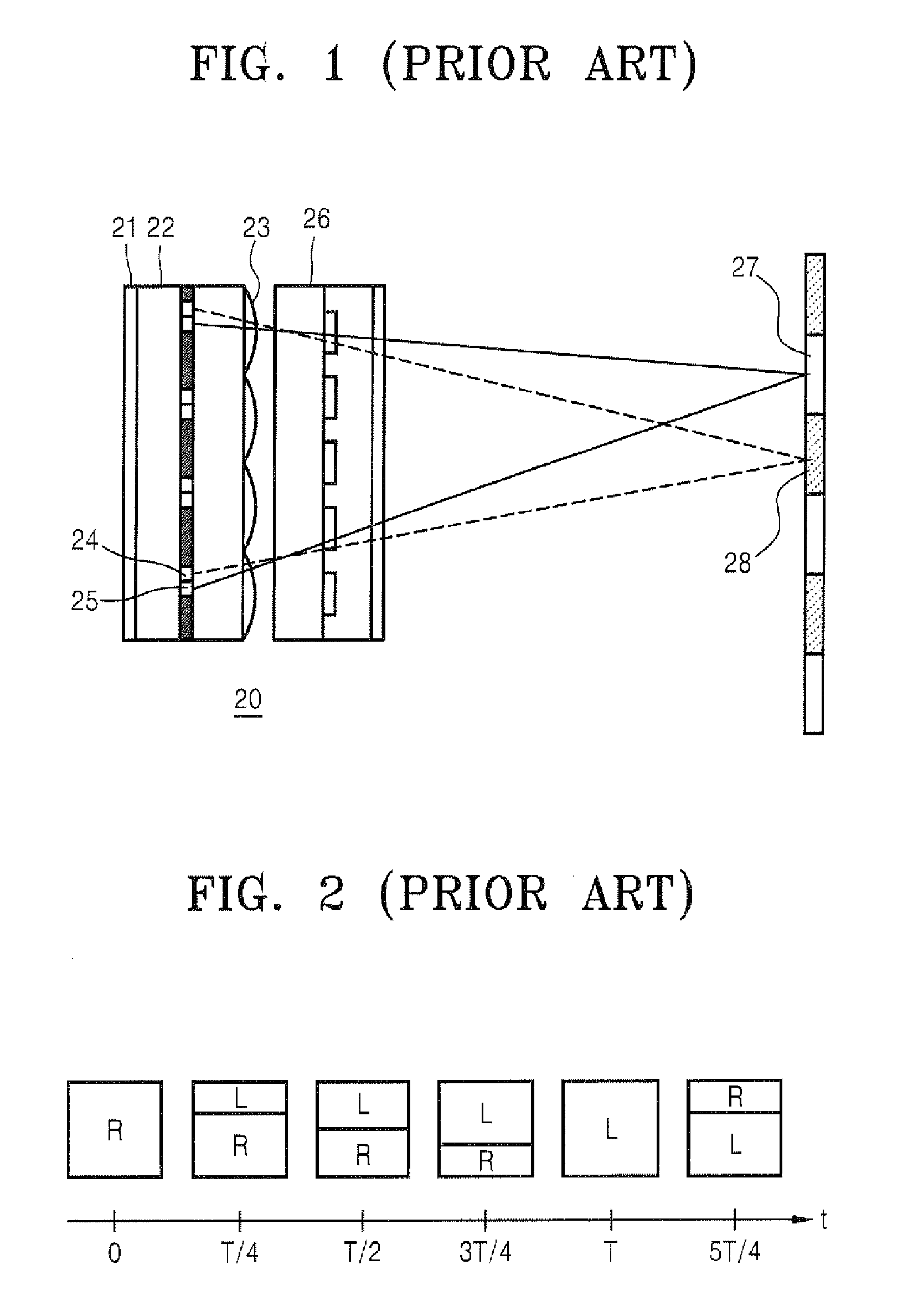
However, as in the above described prior art, when the left eye and right eye cells 24 and 25 of the spatial light modulator 22 are simply turned on and off in alternation, cross-talk is generated between the image for the left eye and the image for the right eye so that the user is not able to view an accurate 3-D image.

Method used


Image

  • High resolution 2d/3d switchable display apparatus
  • High resolution 2d/3d switchable display apparatus
  • High resolution 2d/3d switchable display apparatus

Examples


Embodiment Construction

[0025]Exemplary embodiments of the present invention will now be described more fully with reference to the accompanying drawings. The invention may, however, be embodied in many different forms and should not be construed as being limited to the embodiments set forth herein; rather, these embodiments are provided so that this disclosure will be thorough and complete, and will fully convey the concept of the invention to those skilled in the art. Like reference numerals in the drawings denote like elements, and thus their description will be omitted. In the drawings, the thickness of layers and region are exaggerated for clarity.

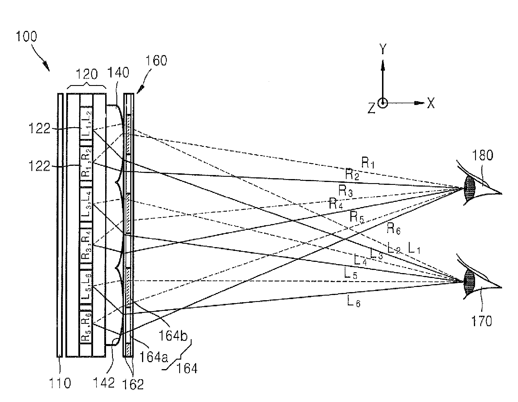
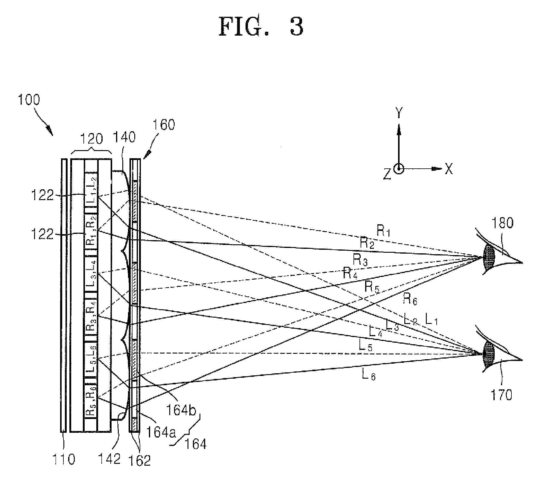
[0026]FIG. 3 is a schematic view illustrating a display apparatus 100 in accordance with an embodiment of the present invention. Referring to FIG. 3, the display apparatus 100 includes a display panel 120, a lenticular lens array 140 dividing light emitted from the display panel 120 to visual regions of left and right eyes 170 and 180 of a viewer, and a spat...


PUM


Abstract

A high resolution 2D / 3D switchable display apparatus includes a display panel having display elements arranged in pixel units and configured to display an image. A lenticular lens array includes a plurality of lenticular lenses arranged in a horizontal direction and dividing light corresponding to a signal emitted from the display panel to visual regions of left and right eyes. A spatial optical modulator includes a plurality of cells configured to switch on or off in synchronization with a vertical scanning time of the display panel, wherein each of the plurality of cells is changed to a transparent or opaque state. The display panel sequentially displays an even field including even sequence data of a left eye image and a right eye image and an odd field including odd sequence data of the left eye image and the right eye image.

Description

CROSS-REFERENCE TO RELATED PATENT APPLICATIONS[0001]This application claims priority from Korean Patent Application No. 10-2006-0074657, filed on Aug. 8, 2006, in the Korean Intellectual Property Office. The priority application is incorporated herein by reference in its entirety.BACKGROUND OF THE INVENTION[0002]1. Field of the Invention[0003]The present invention relates to a high resolution 2D / 3D switchable display apparatus and, more particularly, to a high resolution 2D / 3D switchable display apparatus in which a resolution is not lowered and cross-talk decreases.[0004]2. Description of the Related Art[0005]3D image display devices provide an image for a left eye and an image for a right eye having binocular parallax. The images respectively provided to the left eye and the right eye of a user allow the user to view a stereoscopic 3D image.[0006]In conventional methods, visual fields of images for left and right eyes constituting a stereoscopic pair are divided using a parallax b...

Claims


Application Information

Patent Timeline
IPC IPC(8): G02B27/22G02B30/27G02B30/31
CPCG02B27/2214G02B27/2264H04N13/0454H04N13/0447H04N13/0404H04N13/305H04N13/359H04N13/351G02B30/24G02B30/27G02B30/31
Inventor KOO, JAE-PHILSHESTAK, SERGEYKIM, DAE-SIK
Owner SAMSUNG ELECTRONICS CO LTD
Learn More