
Energy capture system

a technology of energy capture and energy storage, applied in the field of energy capture systems, can solve the problems of inability to manually actuate the locking system, inability to use remotely actuated locking systems, and inability to readily and easily adapt, etc., to facilitate the preservation of aesthetics, and reduce the cost of installation. , the cost of the system and the effect of reducing the cost of installation

Inactive Publication Date: 2008-02-21
SUPERB INDS
View PDF27 Cites 1 Cited by
  • Summary
  • Abstract
  • Description
  • Claims
  • Application Information

AI Technical Summary

Benefits of technology

"The present invention is an energy collection system that is easy to install, has low cost, and can be used for various purposes. The system includes a main body with a photovoltaic cell for capturing light energy, and an adhesive material on the second surface of the main body. The main body can be made from a decorative material that blends in with the mounting structure. The system has a simple design that allows for easy installation and can be adapted to different uses. The technical effects of the invention are that it maintains aesthetic appeal while minimizing installation complexity and cost."

Problems solved by technology

Therefore, in applications where manual actuation of the locking system is not possible, difficult, impractical, or not desirable, the remotely operated locking system provides a convenient method of operating the locking system.
However, in locations where electrical power is not available, use of remotely actuated locking systems is hindered.
However, when the accessory system is used in remote locations, electrical energy may not be readily available.
However, the self contained source of electrical energy typically requires replacement after a period of time.

Method used


Image

  • Energy capture system
  • Energy capture system
  • Energy capture system

Examples


Embodiment Construction

[0029] The objects and advantages of the present invention will become readily manifest to those skilled in the art from reading the following description of a preferred embodiment of the invention when considered in the light of the accompanying drawing. In respect of the method of operation disclosed, the steps presented are exemplary in nature, and thus, the order of the steps is not necessary or critical.

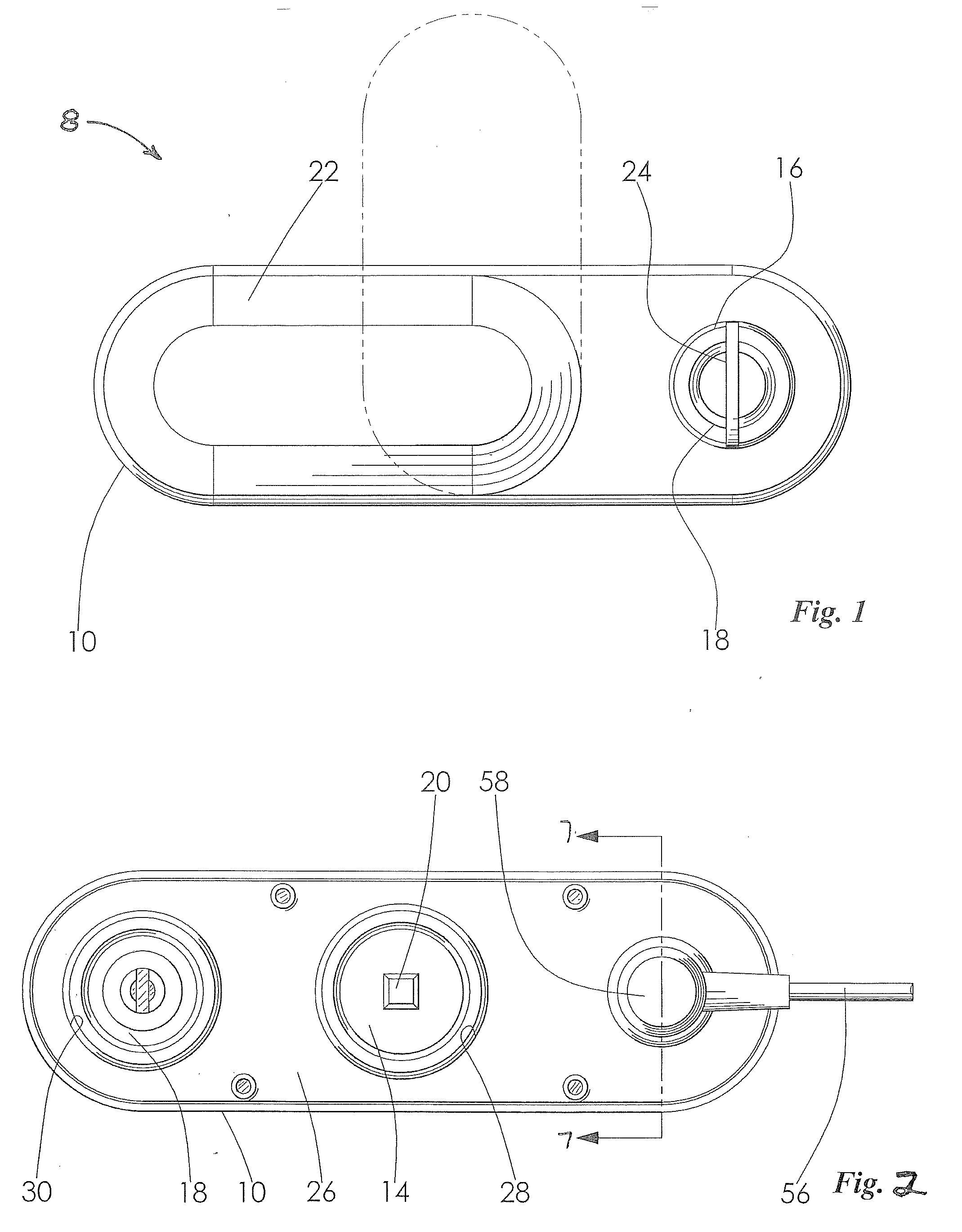
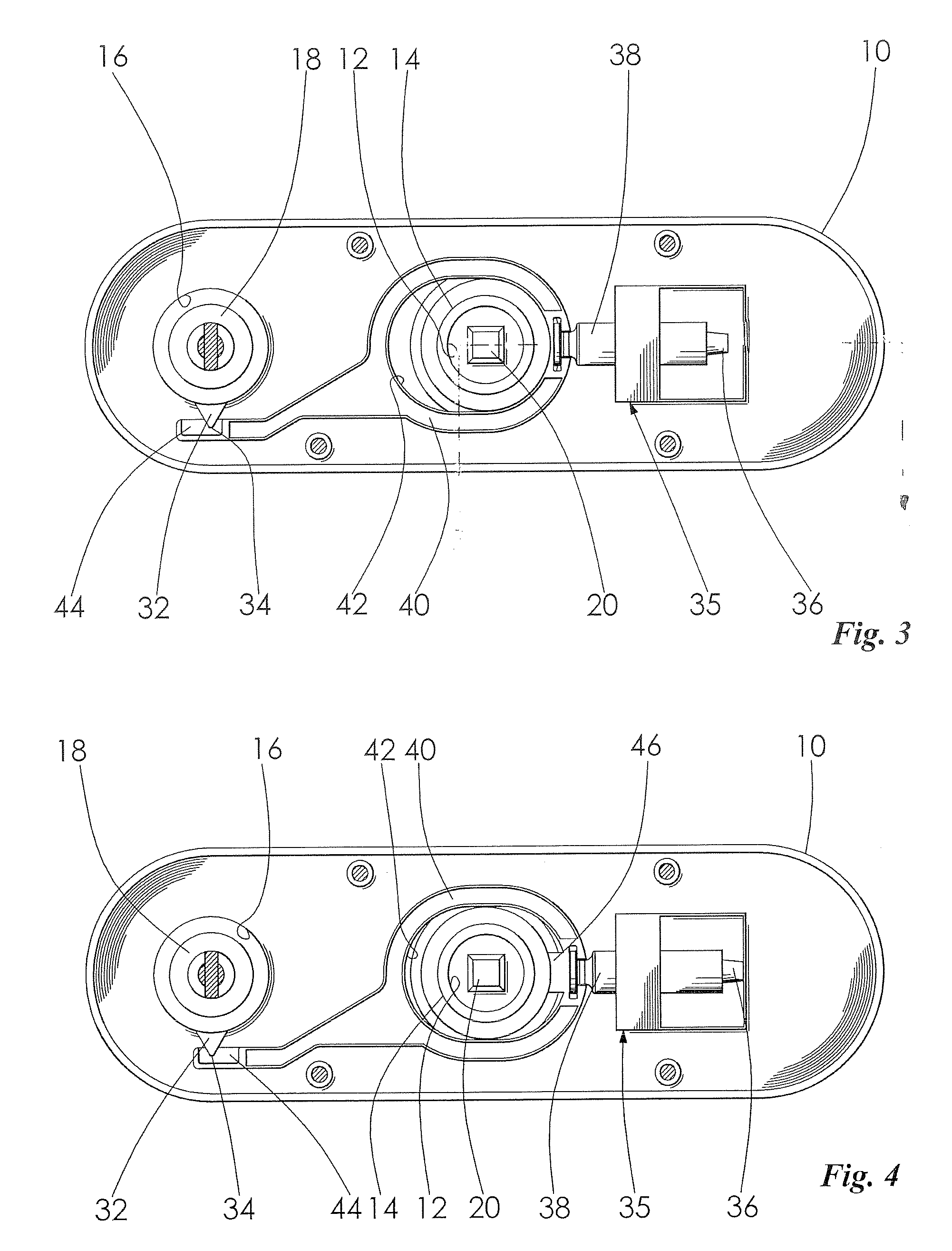
[0030] For exemplary purposes, the invention will be initially described for use with a keyless entry system accessory 8. However, it is understood that the invention can be used with other accessory systems such as signal lighting, general lighting, cigarette lighter adapters, portable storage devices, tool boxes, and the like, for example. Other entry systems and locking mechanisms can also be used with the invention without departing from the scope and spirit thereof. FIG. 1 illustrates the keyless entry system 8 which includes a housing 10. The housing 10 can be formed from...


PUM


Abstract

A solar panel system is disclosed, wherein energy is captured by the solar panel system and stored for re-use in an energy storage device. The solar panel system facilitates a preservation of aesthetics while a complexity of installation, cost of the solar panel system, and cost of installation are minimized.

Description

CROSS-REFERENCE TO RELATED APPLICATION [0001] This application is a Continuation-In-Part of U.S. patent application Ser. No. 11 / 736,835, which claims the benefit of U.S. Prov. Pat. App. Ser. No. 60 / 792,842 filed Apr. 18, 2006; U.S. Prov. Pat. App. Ser. No. 60 / 792,843 filed Apr. 18, 2006; and U.S. Prov. Pat. App. Ser. No. 60 / 843,321 filed Sep. 8, 2006, each of which is incorporated herein by reference in its entirety.FIELD OF THE INVENTION [0002] The present invention relates generally to an energy capture system and more particularly to an energy capture system for use with an accessory system, wherein energy for operating the accessory system is captured by a photovoltaic cell and stored for re-use in an energy storage system. BACKGROUND OF THE INVENTION [0003] A locking system is used for a variety of applications. The applications may include use in a door for a building, a gate, a vehicle, storage units, and the like. The locking systems provide a means for facilitating controll...

Claims


Application Information

Patent Timeline
Patent Type & Authority Applications(United States)
IPC IPC(8): H01L31/04
CPCE05B13/004E05B47/0673G07C2009/0065E05B2047/0058E05B2047/0064E05B2047/0057H02S20/00H02S10/20Y02E10/50Y02E70/30
Inventor MILLER, JOHN J. JR.BRACKNEY, CHARLES R. IIILUECKE, RYAN D.MILLER, DANIEL J.
Owner SUPERB INDS
Learn More