Methods for two-dimensional autofocus in high resolution radar systems

a two-dimensional autofocus and radar technology, applied in the direction of reradiation, measurement devices, instruments, etc., can solve the problems of non-linear target distortion, method only able to remove one-dimensional phase error, and sar image out of focus, so as to achieve fast and sharp parametric autofocus

Active Publication Date: 2008-02-21
MAXAR MISSION SOLUTIONS INC
View PDF20 Cites 43 Cited by
  • Summary
  • Abstract
  • Description
  • Claims
  • Application Information

AI Technical Summary

Benefits of technology

[0009] Exemplary embodiments of the present invention address the drawbacks noted above. By way of example and not by way of limitation, the exemplary embodiments of the present invention provides two-dimensional autofocus methods in a synthetic aperture radar (SAR) system which include: (1) two-dimensional pulse pair product algorithm including shear PGA, eigenvector phase history (“EPH”), shear PGA / EPH); (2) two-dimensional optimization algorithms including parametric one-dimensional estimate / two-dimensional correction, parametric two dimensional estimate / two-dimensional correction, unconstrained two-dimensional nonparametric and constrained two-dimensional nonparametric methods; (3) a two-dimensional geometry filter algorithm; (4) a two-dimensional prominent point processing algorithm; (5) a one-dimensional phase estimate of higher order two dimensional phase errors; and, (6) a fast SHARP parametric autofocus algorithm.

Problems solved by technology

It is well known that phase errors often cause a SAR image to be out of focus.
These phase errors may be the result of uncompensated motion between the SAR antenna and the scene being imaged, algorithm approximations, hardware limitations or propagation effects.
However, these previous methods are only capable of removing one-dimensional phase error.
While one-dimensional autofocus is sufficient for mid-resolution SAR systems where the dwell angle is relatively small, as the resolution of a SAR system increases, non-linear target distortions become more significant due to an increased dwell angle.

Method used


Image

  • Methods for two-dimensional autofocus in high resolution radar systems
  • Methods for two-dimensional autofocus in high resolution radar systems
  • Methods for two-dimensional autofocus in high resolution radar systems

Examples


Embodiment Construction

[0033] The particulars shown herein are by way of example and for purposes of illustrative discussion of the embodiments of the present invention only and are presented in the cause of providing what is believed to be the most useful and readily understood description of the principles and conceptual aspects of the present invention. In this regard, no attempt is made to show structural details of the present invention in more detail than is necessary for the fundamental understanding of the present invention, the description taken with the drawings making apparent to those skilled in the art how the several forms of the present invention may be embodied in practice.

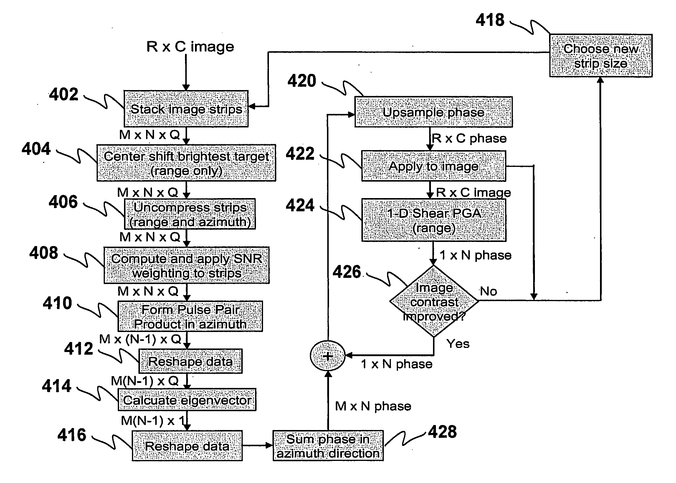
[0034] As mentioned above, previous autofocus techniques, based on one-dimensional estimates, are only capable of removing phase errors which appear as distortions of a target in the cardinal directions. However, SAR imagery which is collected with an antenna utilizing a large dwell angle (for example, UltraSAR) may con...


PUM


Abstract

Provided are two-dimensional autofocus methods in a synthetic aperture radar (SAR) system which include: (1) two-dimensional pulse pair product algorithm including shear PGA, eigenvector phase history (“EPH”), shear PGA/EPH); (2) two-dimensional optimization algorithms including parametric one-dimensional estimate/two-dimensional correction, parametric two dimensional estimate/two-dimensional correction, unconstrained two-dimensional nonparametric and constrained two-dimensional nonparametric methods; (3) a two-dimensional geometry filter algorithm; (4) a two-dimensional prominent point processing algorithm; (5) a one-dimensional phase estimate of higher order two dimensional phase errors; and, (6) a fast SHARP parametric autofocus algorithm.

Description

[0001] This application claims priority to U.S. provisional patent application No. 60 / 836,623, filed Aug. 15, 2006, which is incorporated by reference in its entirety.BACKGROUND OF THE INVENTION [0002] 1. Field of the Invention [0003] The present invention relates to two-dimensional autofocus methods in a Synthetic Aperture Radar (“SAR”) systems. More specifically, the present invention relates to two-dimensional autofocus methods which compensate both on and off-axis distortions in SAR signal history. [0004] 2. Discussion of Background Information [0005] Synthetic aperture radar (“SAR”) systems typically involve a single radar antenna mounted on a moving platform. Data is generally collected using an antenna having a relatively small aperture. Because the antenna is mounted on a moving platform, a series of recurring radar pulse returns from the same target may be received by the antenna at different spatial locations. These returns may then be synthesized during processing, thereb...

Claims


Application Information

Patent Timeline
Patent Type & Authority Applications(United States)
IPC IPC(8): G01S13/90
CPCG01S13/9011G01S13/9019
Inventor CONNELL, SCOTT D.GABL, EDWARD F.RICOY, MARK A.BATTEH, ELIZABETH T.GOODMAN, RON S.
Owner MAXAR MISSION SOLUTIONS INC
Why Eureka
Try Eureka