Recording apparatus and pulse generation controller

a recording apparatus and controller technology, applied in the field of recording apparatus, can solve the problems of deteriorating image formed on recording paper, driver ic needs to stay too long, etc., and achieve the effect of suppressing the lowering of the total recording speed

Inactive Publication Date: 2008-02-21
BROTHER KOGYO KK
View PDF4 Cites 10 Cited by
  • Summary
  • Abstract
  • Description
  • Claims
  • Application Information

AI Technical Summary

Benefits of technology

[0007] In an ink-jet printer as described above, once a printing starts, a pulse pattern output from the driver IC is unstoppable for a predetermined period of time. For example, in a case where a recording head is a line-type head having an ink ejection face extending in a direction perpendicular to a recording medium conveyance direction, the predetermined period of time means a period of time corresponding to a driving unit which is a unit of recording in a printing operation performed on respective print regions of a recording paper which are spaced from each other by a margin with respect to the conveyance direction. In a case where a recording head is a serial-type head which scans in a direction perpendicular to a recording medium conveyance direction, the predetermined period of time means a period of time corresponding to a driving unit which is a unit of recording in a printing operation with an arbitrary number of scannings. That is, if a printing once started is stopped during the above-described predetermined period of time, an image formed on a recording paper deteriorates. It is therefore necessary to determine a restart temperature in such a manner that a temperature of a driver IC does not largely exceed the maximum temperature even when, after a printing is started again, a printing operation corresponding to a next driving unit is completed, that is, even when a temperature of a driver IC becomes highest. However, if a restart temperature is determined so as to make a temperature of the driver IC sufficiently lower than the maximum temperature even when a printing operation corresponding to a next driving unit is completed, the driver IC needs to stay stopped too much. As a result, a total printing speed is lowered in a case where a printing operation including a plurality of continuous driving units is performed.
[0008] An object of the present invention is to provide a recording apparatus and a pulse generation controller which can suppress lowering of total recording speed in a case where a recording including a plurality of continuous driving units is performed.
[0012] According to the first and second aspects, the temperature estimator estimates an increased temperature of the pulse generator based on a next pulse pattern which will be generated by the pulse generator, and the restarter determines, based on the increased temperature, a restart temperature at which the pulse generator will be driven again. This can prevent the pulse generator from being stopped too much. In the recording apparatus according to the first aspect, in a case where a recording is performed through a plurality of continuous driving units, lowering of a total recording speed can be suppressed while not stopping generation of the pulse pattern during a period of time corresponding to a driving unit.

Problems solved by technology

That is, if a printing once started is stopped during the above-described predetermined period of time, an image formed on a recording paper deteriorates.
However, if a restart temperature is determined so as to make a temperature of the driver IC sufficiently lower than the maximum temperature even when a printing operation corresponding to a next driving unit is completed, the driver IC needs to stay stopped too much.

Method used


Image

  • Recording apparatus and pulse generation controller
  • Recording apparatus and pulse generation controller
  • Recording apparatus and pulse generation controller

Examples


Embodiment Construction

[0026] In the following, a certain preferred embodiment of the present invention will be described with reference to the accompanying drawings.

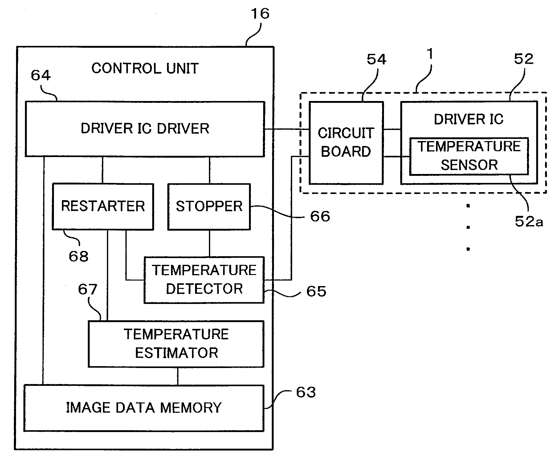
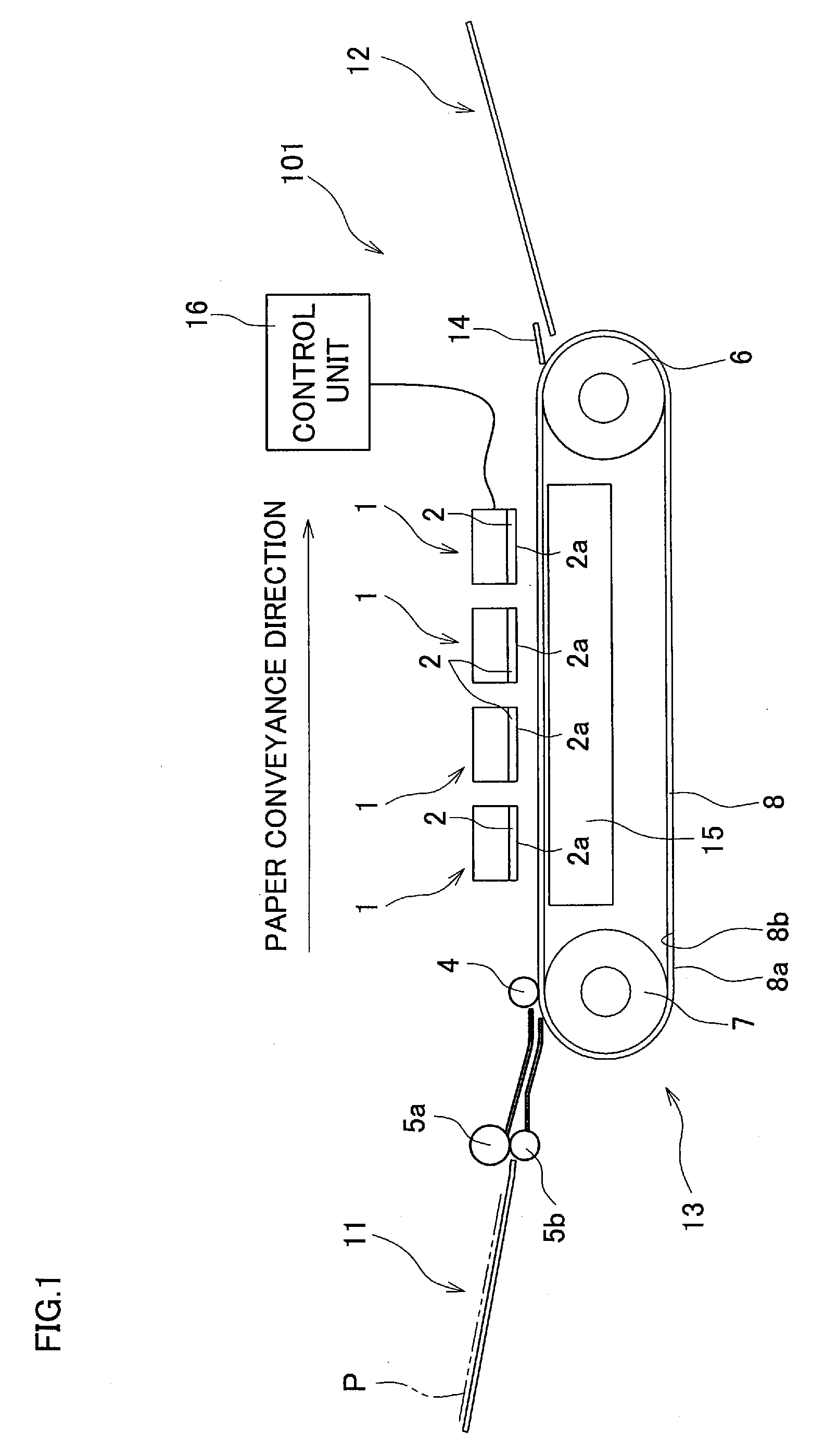
[0027]FIG. 1 is a schematic side view showing a general construction of an ink-jet printer which is one preferred embodiment of the present invention. As shown in FIG. 1, an ink-jet printer 101 which is a recording apparatus is a color ink-jet printer having four ink-jet heads 1. The ink-jet printer 101 has a control unit 16 which controls a whole of the ink-jet printer 101 and in addition functions as a pulse generation controller. The ink-jet printer 101 includes a paper feed unit 11 and a paper discharge unit 12, which are shown in left and right parts of FIG. 1, respectively.

[0028] Formed within the ink-jet printer 101 is a paper conveyance path through which a paper P as a recording medium is conveyed from the paper feed unit 11 toward the paper discharge unit 12. A pair of feed rollers 5a and 5b, which pinches a paper therebetween and...


PUM


Abstract

A recording apparatus of the present invention includes a temperature detector which detects a temperature of a pulse generator, and a driver which drives the pulse generator. When the temperature detector detects a temperature equal to or higher than a predetermined maximum temperature, a stopper stops a driver after driving of the pulse generator corresponding to one or a plurality of driving units is completed. A temperature estimator estimates an increased temperature of the pulse generator based on a pulse pattern which will be generated by the pulse generator thus driven again. A restarter makes the driver restart driving the pulse generator when, after the driver is stopped, a temperature detected by the temperature detector drops to a restart temperature which is equal to or lower than a temperature value obtained by subtracting the increased temperature from the maximum temperature.

Description

CROSS REFERENCE TO RELATED APPLICATION [0001] The present application claims priority from Japanese Patent Application No. 2006-224047, which was filed on Aug. 21, 2006, the disclosure of which is herein incorporated by reference in its entirety. BACKGROUND OF THE INVENTION [0002] 1. Field of the Invention [0003] The present invention relates to a recording apparatus which records an image on a recording medium, and also relates to a pulse generation controller. [0004] 2. Description of Related Art [0005] Known is an ink-jet printer which ejects ink droplets on a recording paper as a recording medium to thereby print an image on the recording paper. As such an ink-jet printer, one including a recording head and a driver IC is known. The recording head includes a passage unit and an actuator. The passage unit has nozzles which eject ink droplets, and pressure chambers which communicate with the nozzles. The actuator applies ejection energy to ink contained in the pressure chambers. T...

Claims


Application Information

Patent Timeline
Patent Type & Authority Applications(United States)
IPC IPC(8): B41J29/38
CPCB41J2/0454B41J2/04563B41J2/04581B41J2/04595B41J2/14209B41J2202/20B41J2002/14225B41J2002/14306B41J2002/14459B41J2002/14491B41J2002/14217
Inventor SUZUKI, KATSUAKI
Owner BROTHER KOGYO KK
Why Eureka
Try Eureka