Image processor and visual field support device

a technology of visual field support and image processor, which is applied in the direction of image enhancement, instruments, television systems, etc., can solve the problems of difficulty in checking the rearview face, difficult to accurately and continuously draw the object in an all-round bird's eye view image, and in principle difficult to see the solid object depending on the colors of the solid object and the background

Active Publication Date: 2008-02-21
SANYO ELECTRIC CO LTD
View PDF5 Cites 64 Cited by
  • Summary
  • Abstract
  • Description
  • Claims
  • Application Information

AI Technical Summary

Problems solved by technology

A driver of an automobile or the like, upon running backward, faces difficulty in checking rearview due to the presence of a blind spot.
However, a solid object placed on the ground surface is viewed differently at different viewpoints of the camera, thus making it difficult, in principle, to accurately and continuously draw this object in an all-round bird's-eye view image.
However, adopting such an averaging technique results in a solid object appearing as a double image in the all-round bird's-eye view image.
Moreover, each image included in the double image is averaged with a background image, which makes it very hard to see the solid object depending on the colors of the solid object and the background.
With this method, however, a plurality of images to be checked by the driver are displayed simultaneously, thus adversely causing confusion, which possibly compromises the security.
However, switching by the manual operation is complicated, and a picture generated only based on the machine operation is not necessarily a picture in which a solid object can be easily recognized.
That is, it is difficult to avoid, by simple switching, the problem that the solid object disappears.

Method used


Image

  • Image processor and visual field support device
  • Image processor and visual field support device
  • Image processor and visual field support device

Examples


example 1

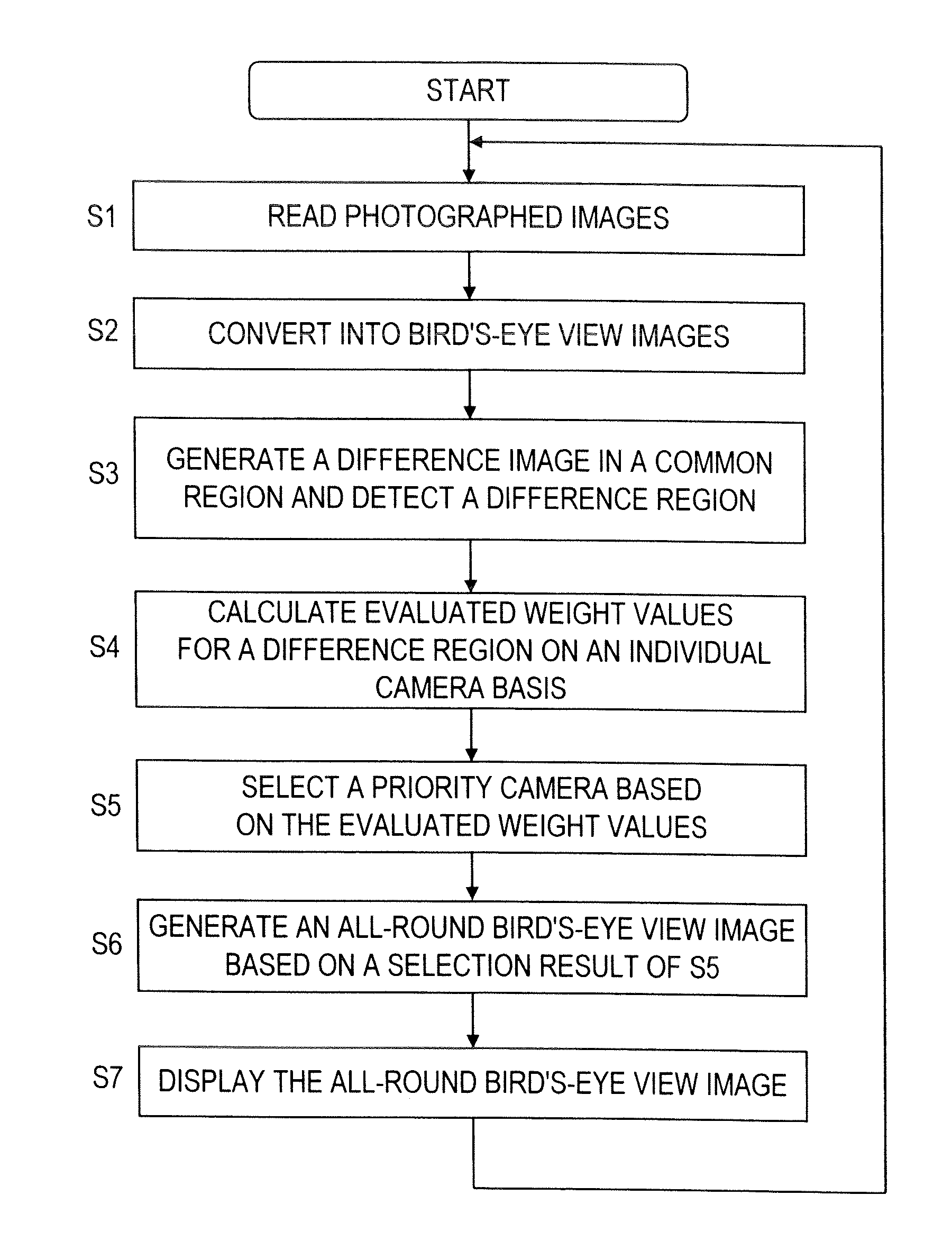
[0098]First, Example 1 will be described. FIG. 9 shows a flowchart representing procedures of processing performed by the visual field support device of FIG. 8 according to Example 1. The processing in steps S2 to S6 shown in FIG. 9 is performed by the image processing section 2, the processing in step S1 is performed by the cameras and the image processing section 2, and the processing in step S7 is performed by the image processing section 2 and the display section 3.

[0099]First, the image processing section 2 reads images photographed by the respective cameras 1F, 1B, 1L, and 1R (step S1). Next, the image processing section 2 converts each of the photographed images into a bird's-eye view image by using conversion table data or the like (step S2), whereby the bird's-eye view images 10F, 10B, 10L, and 10R described above are generated. The conversion table data is previously set in accordance with the equation (7) described above. At this point, each of the photographed images can...

example 2

[0128]Next, Example 2 of the invention will be described. FIG. 24 shows a flowchart representing procedures of processing performed by the visual field support device of FIG. 8 according to Example 2. The processing in steps S12 to S15 shown in FIG. 24 is performed by the image processing section 2, the processing in step S11 is performed by the cameras and the image processing section 2, and the processing in step S16 is performed by the image processing section 2 and the display section 3.

[0129]First, the image processing section 2 reads images photographed by the respective cameras 1F, 1B, 1L, and 1R (step S11). Next, the image processing section 2 converts each of the photographed images into a bird's-eye view image by using conversion table data or the like (step S12), whereby the bird's-eye view images 10F, 10B, 10L, and 10R described above are generated. The conversion table data is previously set in accordance with the equation (7) described above. At this point, each of the...

example 3

[0142]Next, Example 3 of the invention will be described. In Example 3, another example of the method for selecting a priority camera performed in step S14 of FIG. 24 will be described. Example 3 is performed in combination with the Example 2.

[0143]As another example of the method for selecting a priority camera, a first, a second, and a third selection methods will be illustrated. Focusing on the difference region 123 in the common region CFL, the first to third selection methods will be described. Needless to say, a priority camera is selected in the same manner for the other difference regions. The first to third selection methods can be combined arbitrarily as long as no inconsistency arises.

[First Selection Method]

[0144]The first selection method will be described. In the first selection method, distances between the solid object 14 and the cameras are referenced. Recognizing the position of the difference region 123 on the image permits specifying, in an actual space, a distan...


PUM


Abstract

Photographed images from a front camera and a side camera respectively installed at the front and left side of a vehicle are respectively converted into bird's-eye view images, and a synthetic bird's-eye view image is displayed which is obtained by synthesizing the bird's-eye view images. Based on a difference image between the front and side cameras, a difference region where a solid object is drawn is detected from a common region where the both bird's-eye view images overlap. Then, based on position of each pixel forming the difference region, it is evaluated which of the front and side cameras captures the solid object better, and an image of the common region in the synthetic bird's-eye view image is formed based on the image obtained from one of the cameras.

Description

[0001]This nonprovisional application claims priority under 35 U.S.C. § 119(a) on Patent Application No. 2006-224429 filed in Japan on Aug. 21, 2006 and Patent Application No. 2006-224002 filed in Japan on Aug. 21, 2006, the entire contents of which are hereby incorporated by reference.BACKGROUND OF THE INVENTION[0002]1. Field of the Invention[0003]The present invention relates to a visual field support device and a visual field support method, and particularly relates to technology of generating bird's-eye views from images taken by a plurality of cameras installed at a vehicle and then synthesizing the bird's-eye views. The present invention also relates to an image processor for use in the visual field support device.[0004]2. Description of Related Art[0005]A driver of an automobile or the like, upon running backward, faces difficulty in checking rearview due to the presence of a blind spot. Thus, a system has been already developed which is equipped with an in-car camera for mon...

Claims


Application Information

Patent Timeline
Patent Type & Authority Applications(United States)
IPC IPC(8): H04N5/225
CPCG06T3/4038H04N7/181G06T2207/30261G06T2207/10012G06V20/56G06V10/16
Inventor ISHII, YOHEI
Owner SANYO ELECTRIC CO LTD
Why Eureka
Try Eureka