Tape carrier, tape carrier for liquid crystal display device, and liquid crystal display device
- Summary
- Abstract
- Description
- Claims
- Application Information
AI Technical Summary
Benefits of technology
Problems solved by technology
Method used
Image


Examples
first exemplary embodiment
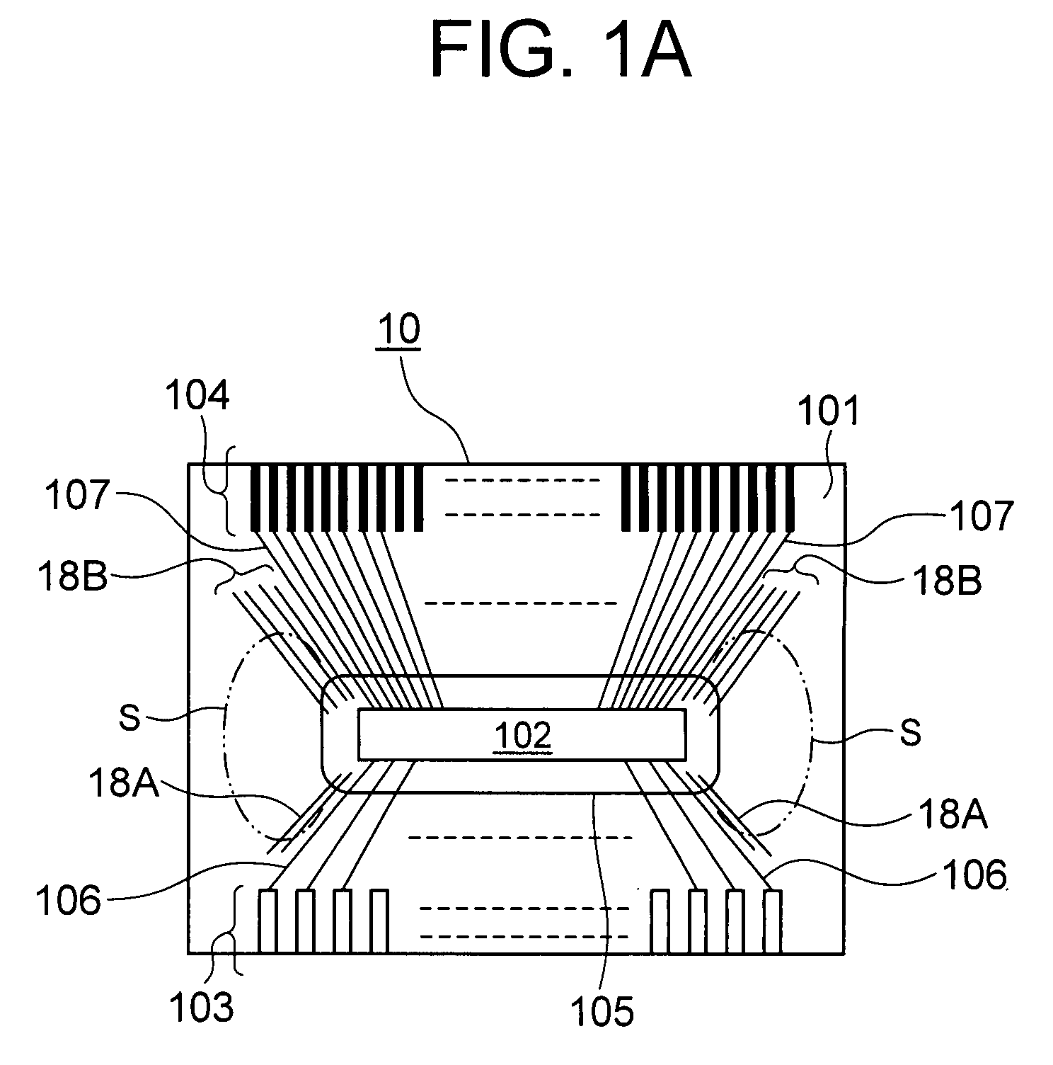
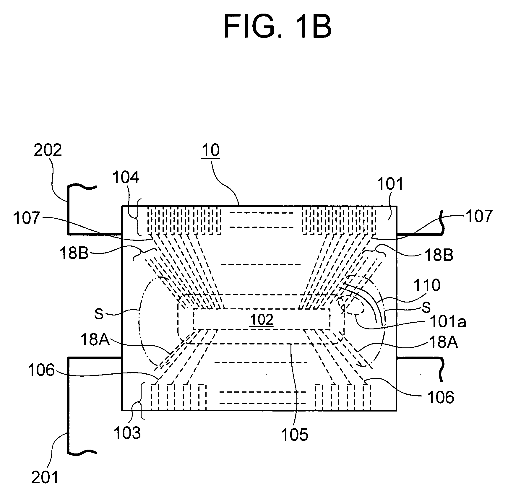
[0029]FIGS. 1A and 1B show a tape carrier for liquid crystal drive serving as the tape carrier of the first exemplary embodiment. Same reference numerals are denoted for components same as in. 5 described above.
(Configuration)
[0030]As shown in FIG. 1A, the tape carrier 10 of the first exemplary embodiment includes an insulation film tape 101, which is a base film, including an input terminal 103 which includes a plurality of terminals on one end and an output terminal 104 which includes a plurality of terminals on the other end; a driver IC 102 serving as a driving IC for an electronic device (e.g., for liquid crystal display device) mounted at the middle part of the insulation film tape 101; input signal lines 106 for connecting the driver IC 102 and the input terminal 103; and output signal lines 107 for connecting the driver IC 102 and the output terminal 104.
[0031]In each free region S corresponding to both left and right side ends of the driver IC 102 in FIG. 1A, linear dummy p...
second exemplary embodiment
[0045]In the tape carrier 20 for liquid crystal drive according to the second exemplary embodiment, each constituting members in the first exemplary embodiment (FIGS. 1A, 1B) described above are arranged, as shown in FIG. 2. In the second exemplary embodiment, an independent base shaped dummy pattern 28 that is of a square shape (trapezoid shape) and that does not have a connecting destination to be electrically connected to is arranged in each free region S positioned between the dummy patterns 18A, 18B, described above, on the respective outer sides of the input signal lines 106 and the output signal lines 107. The feature lies in that the end on the driver IC 102 side of the base shaped dummy pattern 28 is extended into the resin applying region 105 described above.
[0046]The base shaped dummy pattern 28 has a square shape (trapezoid shape) in the present exemplary embodiment, but in the present invention, the base shaped dummy pattern is not limited to the square shape (trapezoid...
third exemplary embodiment
[0049]As shown in FIG. 3, in the tape carrier 30 for liquid crystal drive in the third exemplary embodiment, the output of the driver IC 102 is also output from the short side of the driver IC 102 with output signal lines 107b. Thus, in the exemplary embodiment of FIG. 3, the output signal lines are arranged divided into a total of three groups of the output signal lines 107 from the central portion and two output signal lines 107b from the side portions.
[0050]Among the grouped output signal lines, an independent base shaped dummy pattern 38 of square shape with a narrow width that does not have a connecting destination to be electrically connected to is arranged in a free region Sa (region near dummy pattern 38) between the output signal lines 107 from the central portion and the output signal lines 107b from side portions. The end of each base shaped dummy pattern 38 on the driver IC 102 side is extended into the resin applying region 105. Thus, the rigidity and the elasticity of ...
PUM
 Abstract
Description
Claims
Application Information
 - R&D Engineer
- R&D Manager
- IP Professional
- Industry Leading Data Capabilities
- Powerful AI technology
- Patent DNA Extraction
Browse by: Latest US Patents, China's latest patents, Technical Efficacy Thesaurus, Application Domain, Technology Topic.
© 2024 PatSnap. All rights reserved.Legal|Privacy policy|Modern Slavery Act Transparency Statement|Sitemap