Adaptor for attaching a reference array to a medical instrument having a functional direction or plane

a reference array and medical instrument technology, applied in the field of medical navigation, can solve the problems of limited location of reference adapters on instruments, and achieve the effect of improving the accuracy of diagnostic results

Inactive Publication Date: 2008-02-21
BRAINLAB
View PDF23 Cites 35 Cited by
  • Summary
  • Abstract
  • Description
  • Claims
  • Application Information

AI Technical Summary

Benefits of technology

[0008]In other words, the adapter can be based on the realization that for some instruments, it is not absolutely necessary to completely know the location and position of the functional parts of the instrument. Rather, in some cases it is perfectly sufficient if the reference array only provides an alignment of a particular direction or plane as information for the navigation system. Such a functional direction or plane of the instrument, for example, can be a direction or plane that determines or identifies a working direction of the instrument. Thus, if an instrument, for example, is to be advanced or retracted in a particular direction, it is often sufficient to confirm that this particular direction is maintained. If, during application of the instrument, the adaptor moves the reference array to a predetermined location with respect to such a functional direction or plane of the instrument, it is possible to establish by navigation whether the plane or direction has been maintained during the application. An advantage of this is that navigation can be performed without storing the dimensions of the instrument in a database. This enables navigation of instruments without exchanging or otherwise providing the instrument technical data to the

Problems solved by technology

One disadvantage of this methodology is that either a large database of pre-calibrated instruments and reference arrays need be provided and maintained, or each instrument that is provided with a reference adaptor has to be assigned to the reference adaptor, and the shape of the in

Method used


Image

  • Adaptor for attaching a reference array to a medical instrument having a functional direction or plane
  • Adaptor for attaching a reference array to a medical instrument having a functional direction or plane
  • Adaptor for attaching a reference array to a medical instrument having a functional direction or plane

Examples


Embodiment Construction

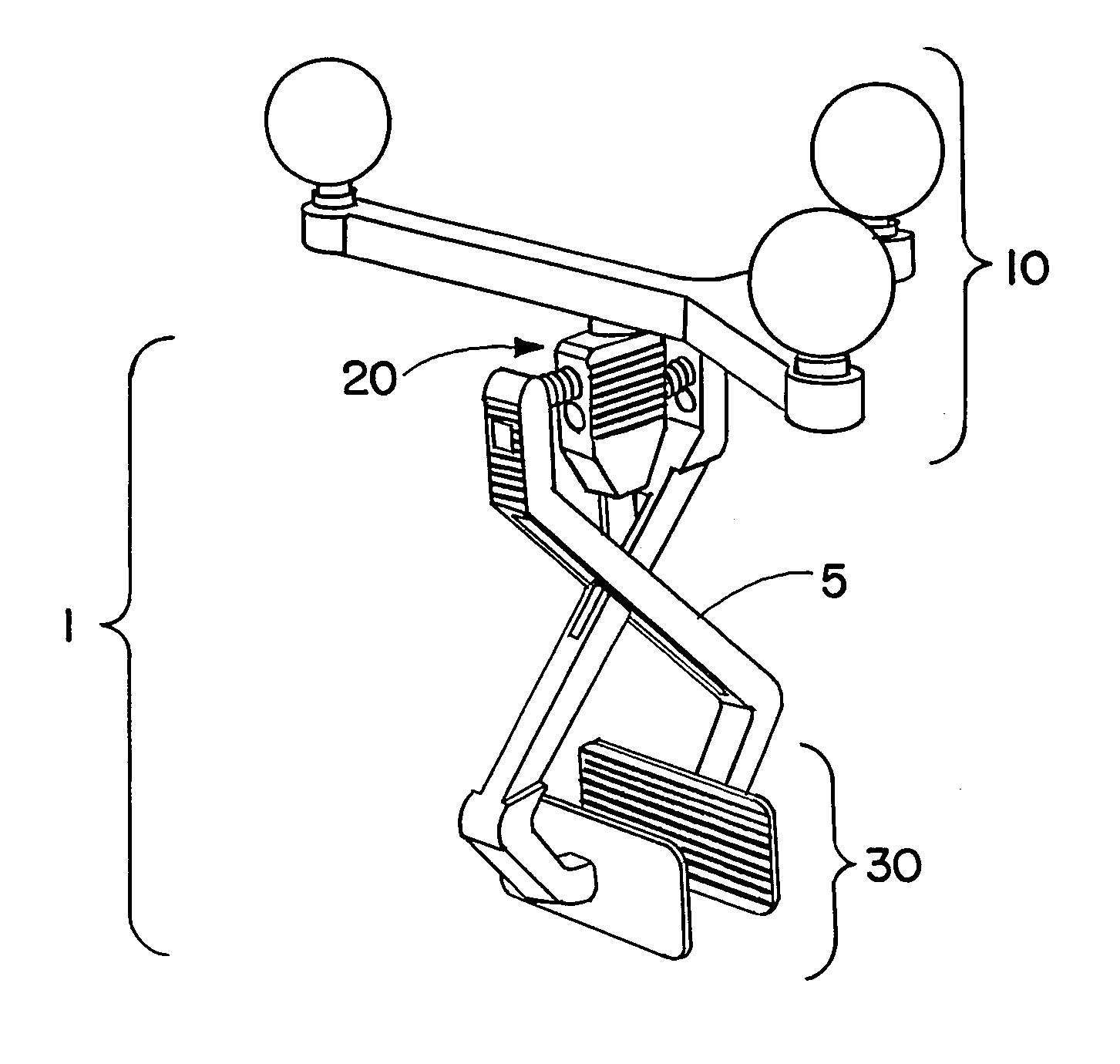
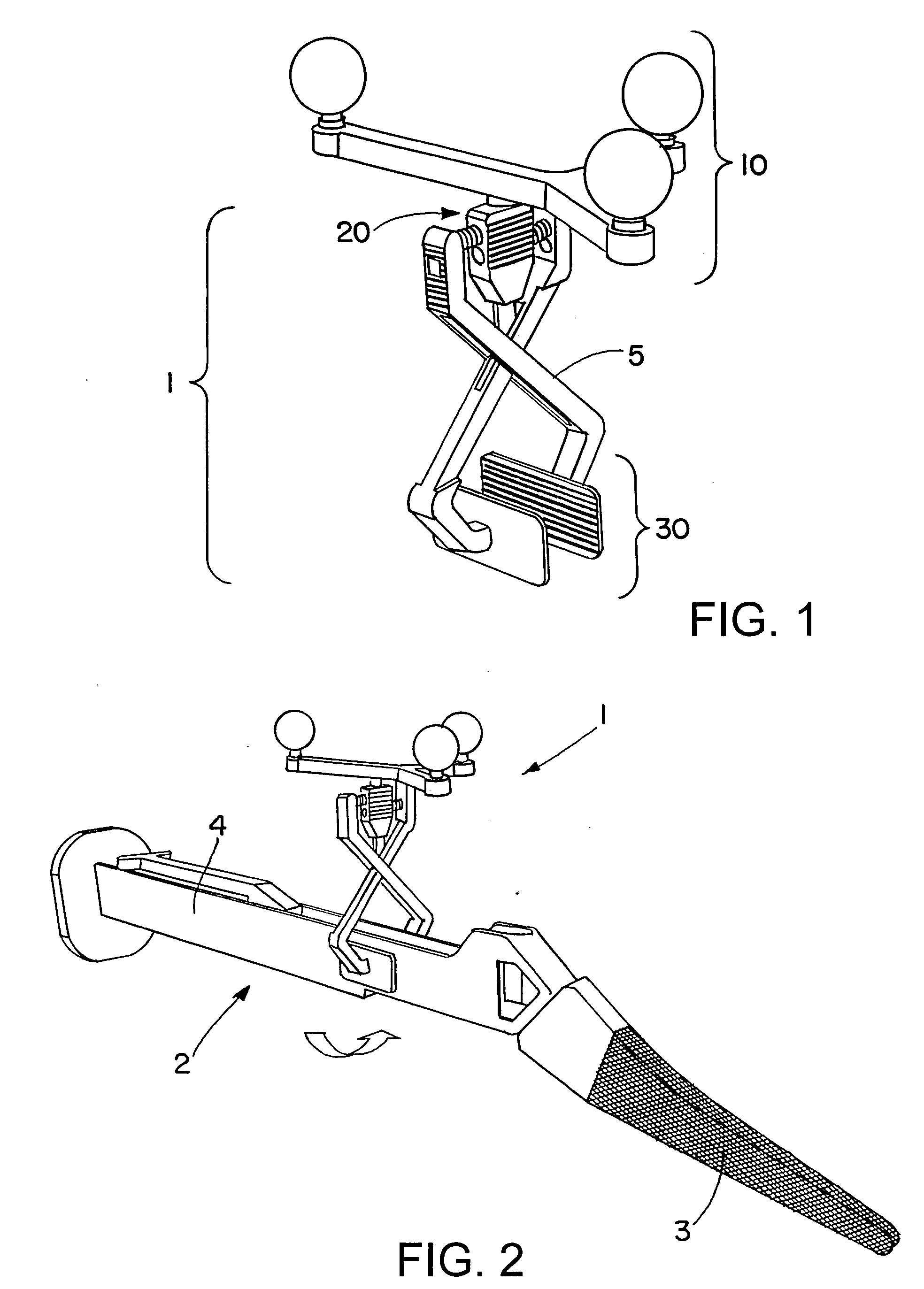
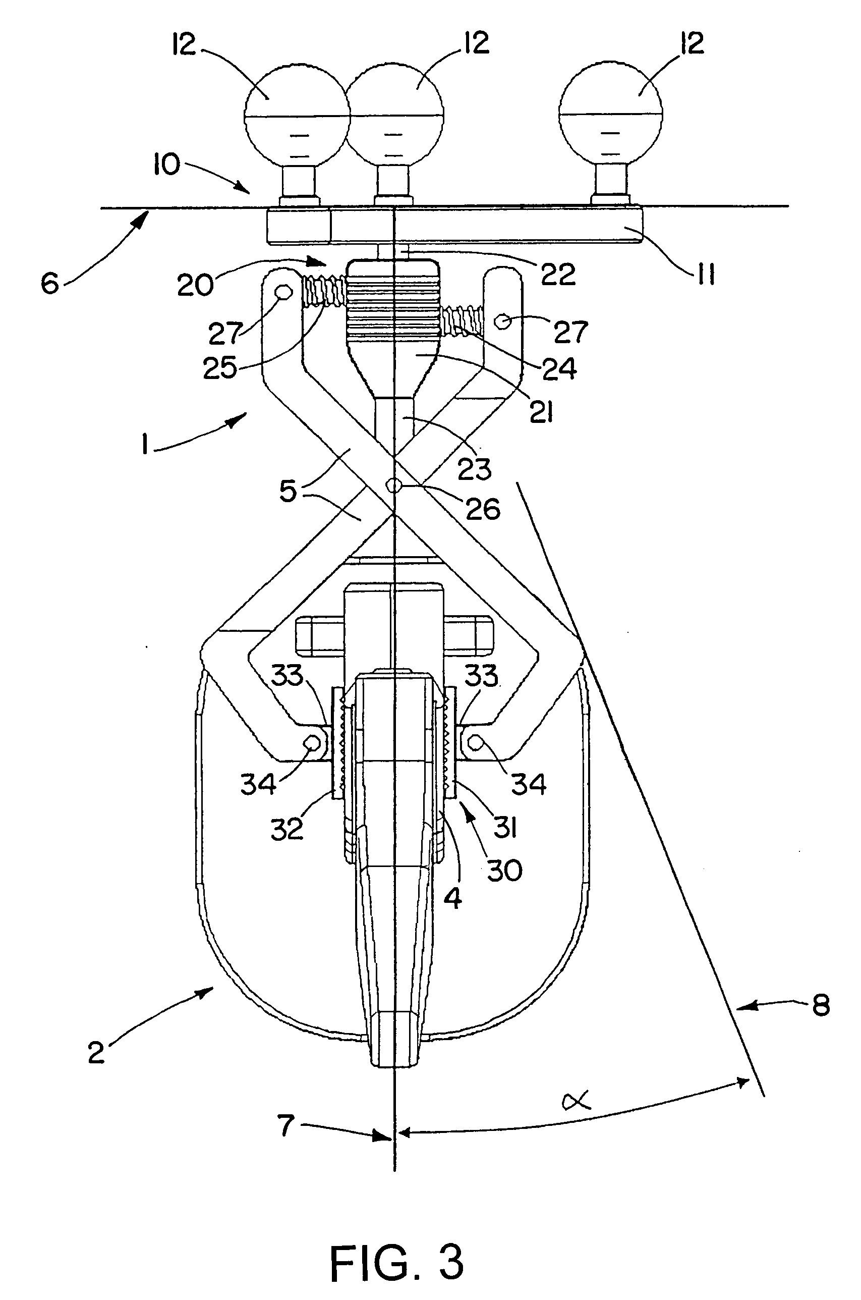
[0020]FIGS. 1 and 2 show a perspective view of the main components of an exemplary adaptor attaching system for reference arrays, while FIG. 3 provides a schematic view of the adapter attaching system. The adaptor 1 can broadly comprise a reference array mount 20 for mounting a reference array 10 to the adapter 1, an instrument engagement section 30 for coupling the adapter 1 to an instrument, and a coupling mechanism 5 coupling the reference array mount 20 to the instrument engagement section 30. The adapter 1 also may include the reference array 10, which can comprise a plurality of markers 12 mounted on a star-like marker support 11, for example. The adaptor 1, via the instrument engagement section 30, can be clamped to the instrument together with the reference array 10, and is shown in this state in FIG. 2 on a bone broach 2 having a handle 4 and a broaching portion 3.

[0021]In the state shown in FIG. 2, the broach 2 can be navigated, for example, in a navigation environment suc...


PUM


Abstract

An adaptor for attaching a reference array to a medical instrument, said instrument having a functional direction or plane includes a reference array mount for attaching the reference array to the adapter, an instrument engagement section for attaching the adaptor to the instrument, and a self-aligning coupling mechanism. The coupling mechanism is coupled to the reference array mount and to the instrument engagement section and is operative to move the reference array attached to the reference array mount to a predetermined location relative to the functional direction or plane of the instrument when the instrument engagement section is attached to the instrument.

Description

RELATED APPLICATION DATA[0001]This application claims priority of U.S. Provisional Application No. 60 / 823,846 filed on Aug. 29, 2006, which is incorporated herein by reference in its entirety.FIELD OF THE INVENTION[0002]The invention relates to medical navigation and, more particularly, to an adaptor for attaching a reference array to a medical instrument having at least one functional plane.BACKGROUND OF THE INVENTION[0003]Reference arrays serve to make an instrument visible to and trackable by a medical tracking and navigation system. It is also possible to identify each individual reference array (e.g., based on a specific arrangement of markers on the reference array) and, therefore, identify each individual instrument attached to the reference array.[0004]In some cases, interfaces configured in a particular way may be provided on instruments, and reference arrays are then fastened thereto using an adaptor. These adaptors can comprise a mounting for the reference array and an in...

Claims


Application Information

Patent Timeline
IPC IPC(8): A61B19/00
CPCA61B19/54A61B2019/5483A61B2017/00477A61B2090/3983A61B90/39
Inventor WAGNER, BENJAMINNEUBAUER, TIMOSCHUBERT, MARIO
Owner BRAINLAB
Why Eureka
Try Eureka