

Scatter Attenuation Tomography
- Summary
- Abstract
- Description
- Claims
- Application Information
AI Technical Summary
Problems solved by technology
Method used
Image

Examples
Embodiment Construction
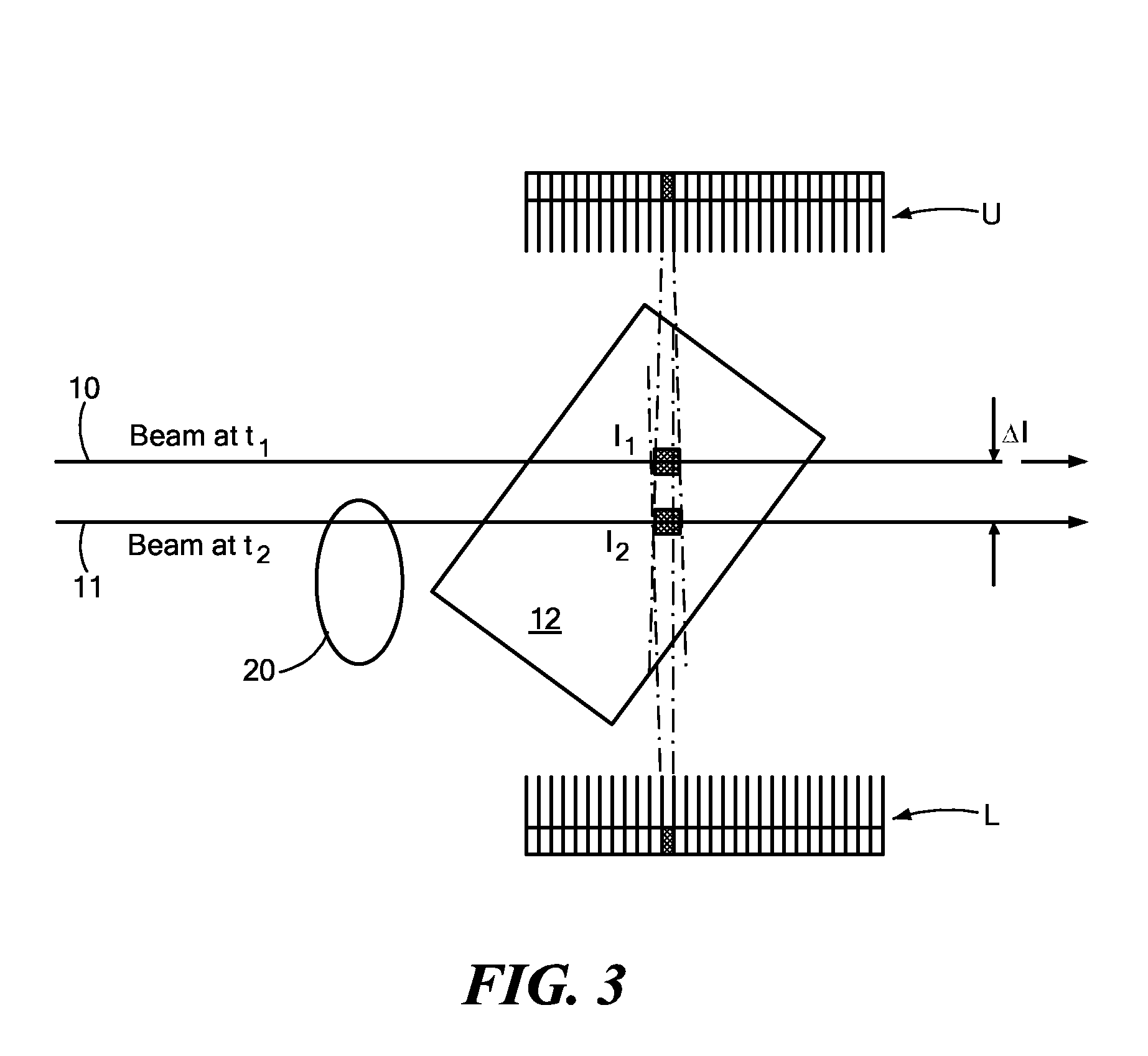
[0028] The current invention builds upon the teachings of U.S. Pat. No. 5,930,326 by describing a simple and elegant method for determining a much more accurate measurement of the density of concealed organic objects. In accordance with preferred embodiments of the present invention, the side-scatter distribution is detected in two detector arrays. The method allows for a full three-dimensional reconstruction of the organic contents of the container, along with the more accurate density determination that could be obtained using the methods taught in U.S. Pat. No. 5,930,326.
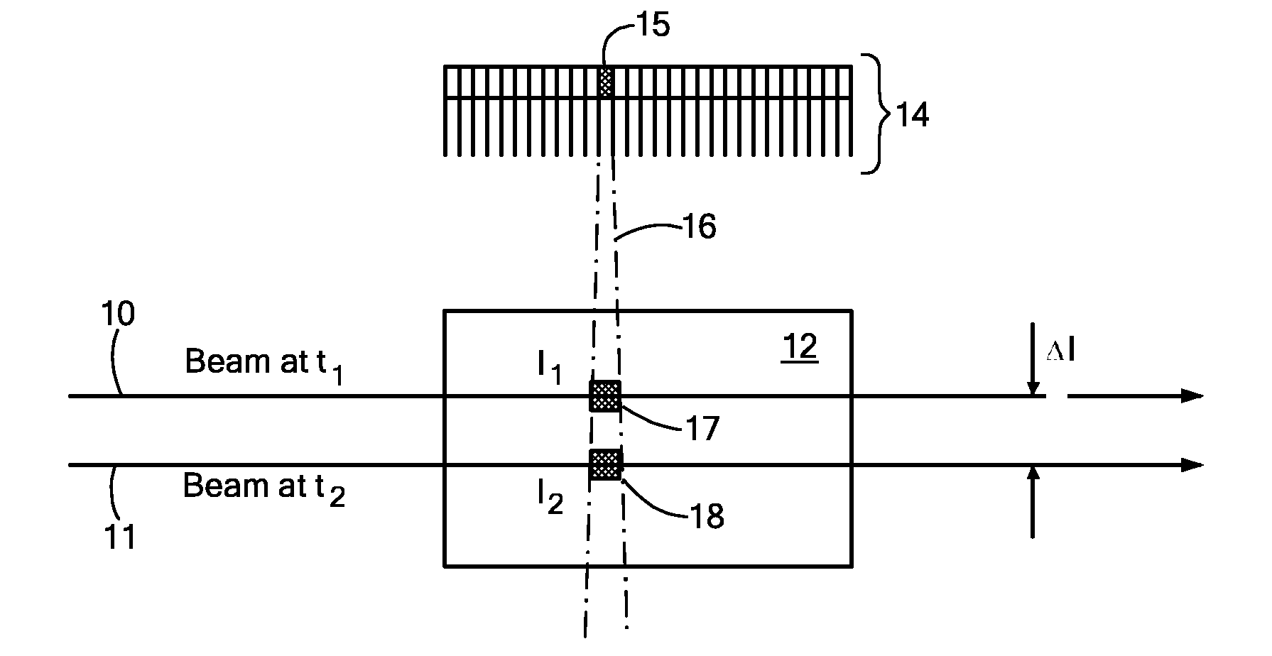
[0029] As now described with reference to FIG. 1, Scatter Attenuation Tomography, generally, looks at the fall-off, in the side-scattered radiation, from a raster-scanning x-ray beam as the beam moves deeper into an object of interest.
[0030] It is to be noted that while the present description refers to an incident beam 10 of penetrating radiation as an x-ray beam, it is to be understood that any beam of penetr...
PUM
 Abstract
Description
Claims
Application Information