Turbine airfoil cooling system with bifurcated and recessed trailing edge exhaust channels

Inactive Publication Date: 2008-02-28
SIEMENS ENERGY INC
View PDF19 Cites 37 Cited by
  • Summary
  • Abstract
  • Description
  • Claims
  • Application Information

AI Technical Summary

Benefits of technology

[0005]This invention relates to a turbine airfoil cooling system for a turbine airfoil used in turbine engines. In particular, the turbine airfoil cooling system may include one or more internal cavities positioned between outer walls of a generally elongated, hollow airfoil of the turbine airfoil. The cooling system may include one or more trailing edge cooling channels positioned within the generally elongated, hollow airfoil and proximate to a trailing edge and may be bifurcated and recessed from the airfoil external surface to minimize shear mixing at the trailing edge, thereby reducing aerodynamic loss while maintaining high f

Problems solved by technology

In addition, turbine blades often contain cooling systems for prolonging the life of the blades and reducing the likelihood of failure as a result of excessive temperatures.
However, centrifugal forces and air flow at boundary layers often prevent some areas of the turbine blade from being adequately cooled, which results in the formation of localized hot spots.
Localized hot spots, depending on their location, can reduce the useful

Method used


Image

  • Turbine airfoil cooling system with bifurcated and recessed trailing edge exhaust channels
  • Turbine airfoil cooling system with bifurcated and recessed trailing edge exhaust channels
  • Turbine airfoil cooling system with bifurcated and recessed trailing edge exhaust channels

Examples


Embodiment Construction

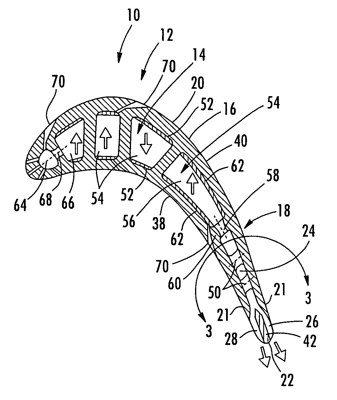
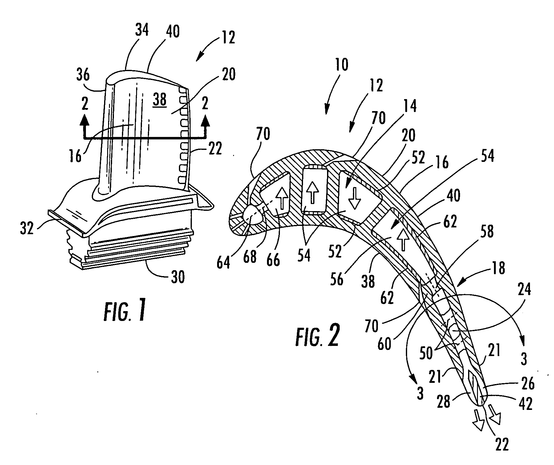
[0019]As shown in FIGS. 1-5, this invention is directed to a turbine airfoil cooling system 10 for a turbine airfoil 12 used in turbine engines. In particular, the turbine airfoil cooling system 10 may include one or more internal cavities 14, as shown in FIG. 2, positioned between outer walls 16 of a generally elongated, hollow airfoil 20 of the turbine airfoil 12. The cooling system 10 may include one or more trailing edge cooling channels 18 positioned within the generally elongated, hollow airfoil 20. The trailing edge cooling channels 18 may be positioned proximate to a trailing edge 22 and may be bifurcated to minimize shear mixing at the trailing edge 22, thereby reducing aerodynamic loss while maintaining high film cooling effectiveness for the trailing edge 22. In at least one embodiment, the trailing edge cooling channel 18 may include a central trailing edge cooling channel 24, a suction side trailing edge cooling channel 26 extending from the central trailing edge coolin...


PUM


Abstract

A cooling system for a turbine airfoil of a turbine engine having a trailing edge cooling channel with bifurcated exhaust channels formed by suction and pressure side trailing edge cooling channels in fluid communication with a central trailing edge cooling channel. The suction and pressure side trailing edge cooling channels may be separated with a trailing edge rib. The suction and pressure side trailing edge cooling channels may be recessed from the airfoil external surface to control the flow of cooling fluids from the cooling system such that the exhaust flow minimizes shear mixing and thus lowers the aerodynamic loss yet maintains high film cooling effectiveness for the airfoil trailing edge.

Description

FIELD OF THE INVENTION[0001]This invention is directed generally to turbine airfoils, and more particularly to cooling systems in hollow turbine airfoils.BACKGROUND[0002]Typically, gas turbine engines include a compressor for compressing air, a combustor for mixing the compressed air with fuel and igniting the mixture, and a turbine blade assembly for producing power. Combustors often operate at high temperatures that may exceed 2,500 degrees Fahrenheit. Typical turbine combustor configurations expose turbine blade assemblies to these high temperatures. As a result, turbine blades must be made of materials capable of withstanding such high temperatures. In addition, turbine blades often contain cooling systems for prolonging the life of the blades and reducing the likelihood of failure as a result of excessive temperatures.[0003]Typically, turbine blades are formed from a root portion having a platform at one end and an elongated portion forming a blade that extends outwardly from t...

Claims


Application Information

Patent Timeline
IPC IPC(8): F01D5/18
CPCF01D5/187F05D2240/304F05D2240/122
Inventor LIANG, GEORGE
Owner SIEMENS ENERGY INC
Why Eureka
Try Eureka