Methods and apparatus for machining a coupling

a coupling and coupling technology, applied in the field of couplings, can solve the problems of frequent process setup changes, time-consuming and labor-intensive tasks,

Inactive Publication Date: 2008-02-28
GENERAL ELECTRIC CO
View PDF20 Cites 30 Cited by
  • Summary
  • Abstract
  • Description
  • Claims
  • Application Information

AI Technical Summary

Problems solved by technology

As such, manufacturing such components may be a time-consuming and laborious task.
However, such processes require frequent process setup changes to accommodate different component configurations based on the demand for each product.

Method used


Image

  • Methods and apparatus for machining a coupling
  • Methods and apparatus for machining a coupling
  • Methods and apparatus for machining a coupling

Examples


Embodiment Construction

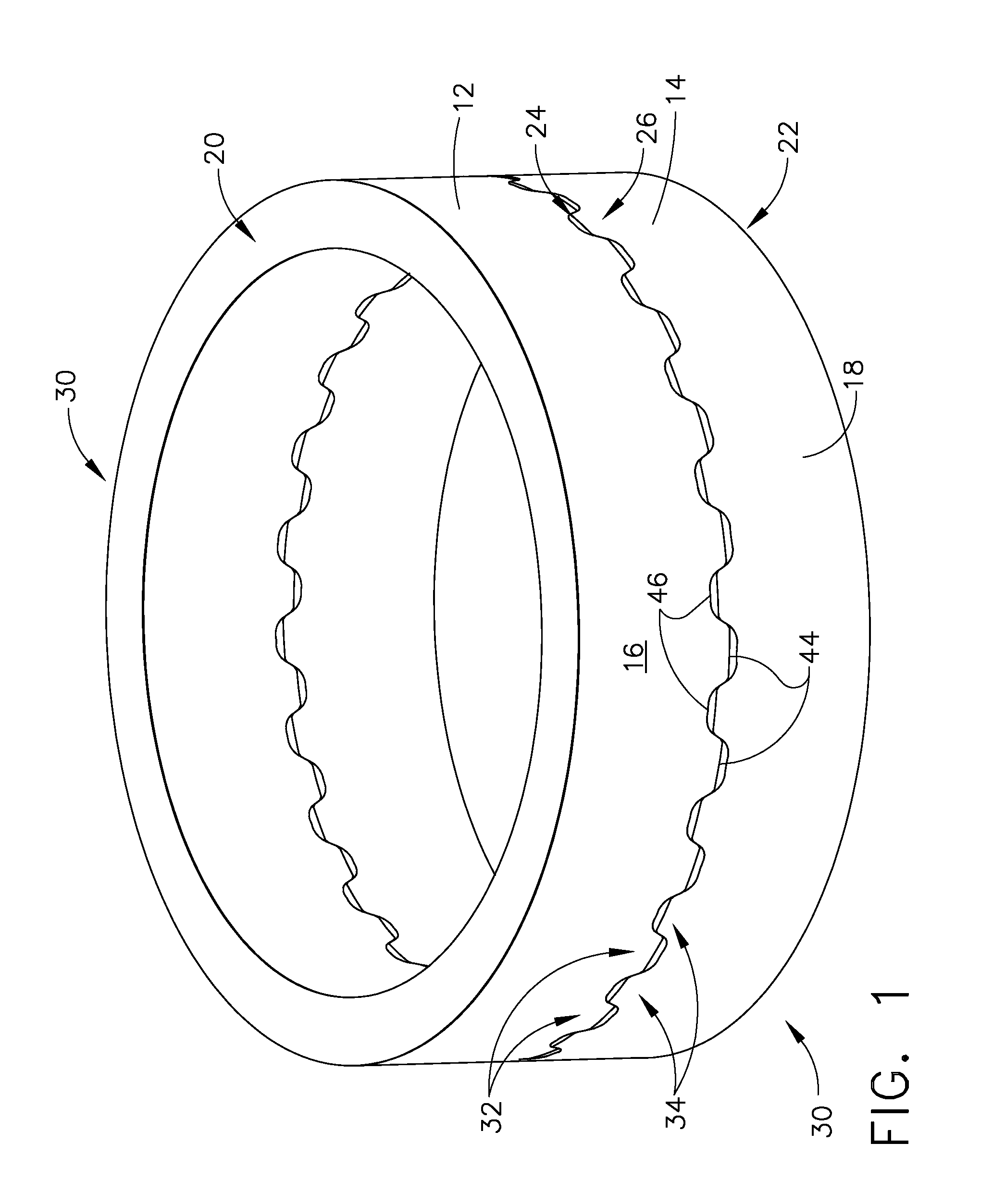
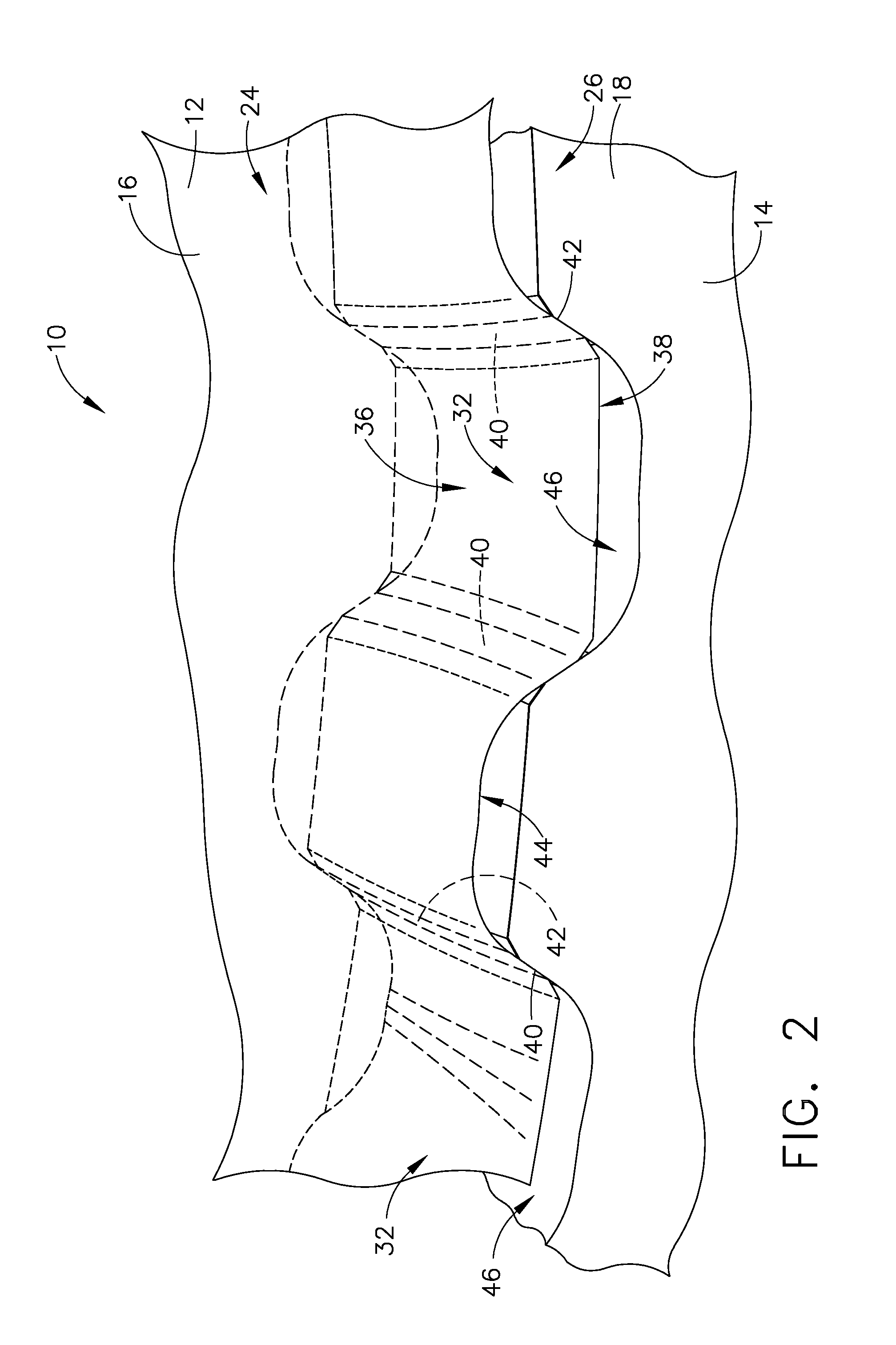
[0016]FIG. 1 is a perspective view of an exemplary coupling 10. FIG. 2 is a perspective view of a portion of coupling 10. Coupling 10 includes a first coupling member 12 and a second coupling member 14. Coupling members 12 and 14 each include a substantially cylindrically shaped body 16 and 18, respectively. Bodies 16 and 18 are each annular and extend between a respective first end 20 or 22 and a respective second end 24 or 26. A central axis 27 respectively, extends through bodies 16 and 18. A bore 28 and 30 extends through each respective body 16 and 18 between each respective first end 20 or 22 and each respective second end 24 and 26. More specifically, bores 28 and 30 are substantially concentric with respect to bodies 16 and 18, respectively.

[0017] A plurality of teeth 32 extend outwardly from each respective body second end 28 and 30. More specifically, each tooth 32 extends outwardly from a respective root 36 to a respective tip 38. More specifically, each tip 38 is trunca...


PUM

PropertyMeasurementUnit
timeaaaaaaaaaa
axis of rotationaaaaaaaaaa
abrasiveaaaaaaaaaa

Abstract

A method facilitates fabricating a coupling including a first annular coupling member and a second annular coupling member. The method comprises coupling the first coupling member to a machine assembly that includes a plurality of grinding wheels coupled to a tool storage member, machining a plurality of troughs in the first coupling member using at least one of the plurality of grinding wheels, such that at least one projection is defined between adjacent troughs, coupling the second coupling member to the machine assembly, and machining a plurality of troughs in the second coupling member using at least one of the plurality of grinding wheels, such that the second coupling member is configured to rotatably couple to the first coupling member.

Description

BACKGROUND OF THE INVENTION [0001] This invention relates generally to couplings, and more specifically to methods and apparatus for machining a coupling. [0002] Components manufactured for turbine engines may have tight tolerances and / or rigid specifications that must be satisfied for the components to function properly with other turbine engine systems. For example, rotating components within the engine may be coupled with multi-piece couplings that are rotatably mated together. Because the components are mated together, manufacturing the components within the rigid tolerances may be essential to the performance of the component. [0003] As such, manufacturing such components may be a time-consuming and laborious task. To facilitate streamlining the manufacturing process of such components, at least some known processes used a single-purpose machine that facilitates processing each component in a single-piece flow. However, such processes require frequent process setup changes to a...

Claims


Application Information

Patent Timeline
Patent Type & Authority Applications(United States)
IPC IPC(8): B24B7/00
CPCB23F15/06B24B27/0061Y10T483/174B24B53/062B24D7/10B24B41/06
Inventor BURGESS, GREG M.
Owner GENERAL ELECTRIC CO
Why Eureka
Try Eureka