Simplified implantable hearing aid transducer apparatus

a transducer and implantable technology, applied in the field of implantable hearing aid transducers, can solve the problems of difficult interconnection between, both movable and sealed, and achieve the effects of simplifying, simplifying, and improving the performance of hearing aid transducers

Inactive Publication Date: 2008-02-28
COCHLEAR LIMITED
View PDF51 Cites 96 Cited by
  • Summary
  • Abstract
  • Description
  • Claims
  • Application Information

AI Technical Summary

Benefits of technology

[0006] In view of the foregoing, an object of the present invention is to simplify, and otherwise improve, hearing aid transducers. Another object of the present invention is to simplify, and otherwise improve, hearing aid transducer implantation procedures. A related object of the present invention is to simplify and otherwise improve orientation and alignment methods and apparatus for hearing aid transducer implantation.
[0019] It should be noted that, advantageously, the entire seal of the present aspect moves with the one of the magnet and coil connected to the actuator or tube, and therefore, fatigue on the material is reduced to enhance the durability and reliability of the seal. Those skilled in the art will appreciate the significant advantage over seals, having portions of the seal move relative to other portions of the seal to accommodate movement between components connected to the different portions. In other words, while the seal of the present invention moves with the movable members of the transducer, the seal is less susceptible to mechanical failure due to the movement of the entire seal, as opposed to only a portion of the seal.
[0024] According to another feature of the present aspect, the retaining member may be connected to the resilient member or integrally formed as a single unit. Alternatively, the retaining member and resilient member may be separate structures that cooperatively operate to capture the rotatable member in the desired orientation. In this regard, the rotatable member may be a portion of a transducer housing such as the above-described housing that is designed for rotation relative to the mounting apparatus. In this regard, the retention apparatus may be designed to exert sufficient force on the rotatable member to capture the rotatable member in a fixed orientation, while still permitting rotation of the rotatable member upon application of a predetermined amount of force. Advantageously, this allows for pre-assembly of the mounting apparatus, the rotatable member, and the retention apparatus, prior to implantation in the patient to reduce implantation steps, while permitting orientation of the rotatable member subsequent to implantation, to align the actuator with a desired interface point on the auditory component.
[0025] According to another feature of the present aspect, the retention apparatus may further include a base interconnected to the resilient member distal to the retaining member. According to this characterization, the base may further include a second interface to increase the frictional coefficient between the pivotable member and the base when the connector is in the locked position. For instance, the base may include a roughed surface or material having a higher frictional coefficient than the base, such that the retention force between the connector and the pivotable member is increased.

Problems solved by technology

Orienting and positioning an implantable transducer for interfacing with a component of the auditory system, e.g. the ossicles, poses numerous challenges.
Providing an interconnection between a movable member, such as an actuator, and the transducer, however, that is both movable and sealed is difficult as such an interconnection necessitates forming a seal between the actuator and the transducer housing that does not interfere with driving or moving of the actuator in response to transducer drive signals.

Method used


Image

  • Simplified implantable hearing aid transducer apparatus
  • Simplified implantable hearing aid transducer apparatus
  • Simplified implantable hearing aid transducer apparatus

Examples


Embodiment Construction

[0053] Reference will now be made to the accompanying drawings, which at least assist in illustrating the various pertinent features of the present invention. In this regard, the following description is presented for purposes of illustration and description and is not intended to limit the invention to the form disclosed herein. Consequently, variations and modifications commensurate with the following teachings, and skill and knowledge of the relevant art, are within the scope of the present invention. The embodiments described herein are further intended to enable others skilled in the art to utilize the invention in such, or other embodiments, and with various modifications required by the particular application(s) or use(s) of the present invention.

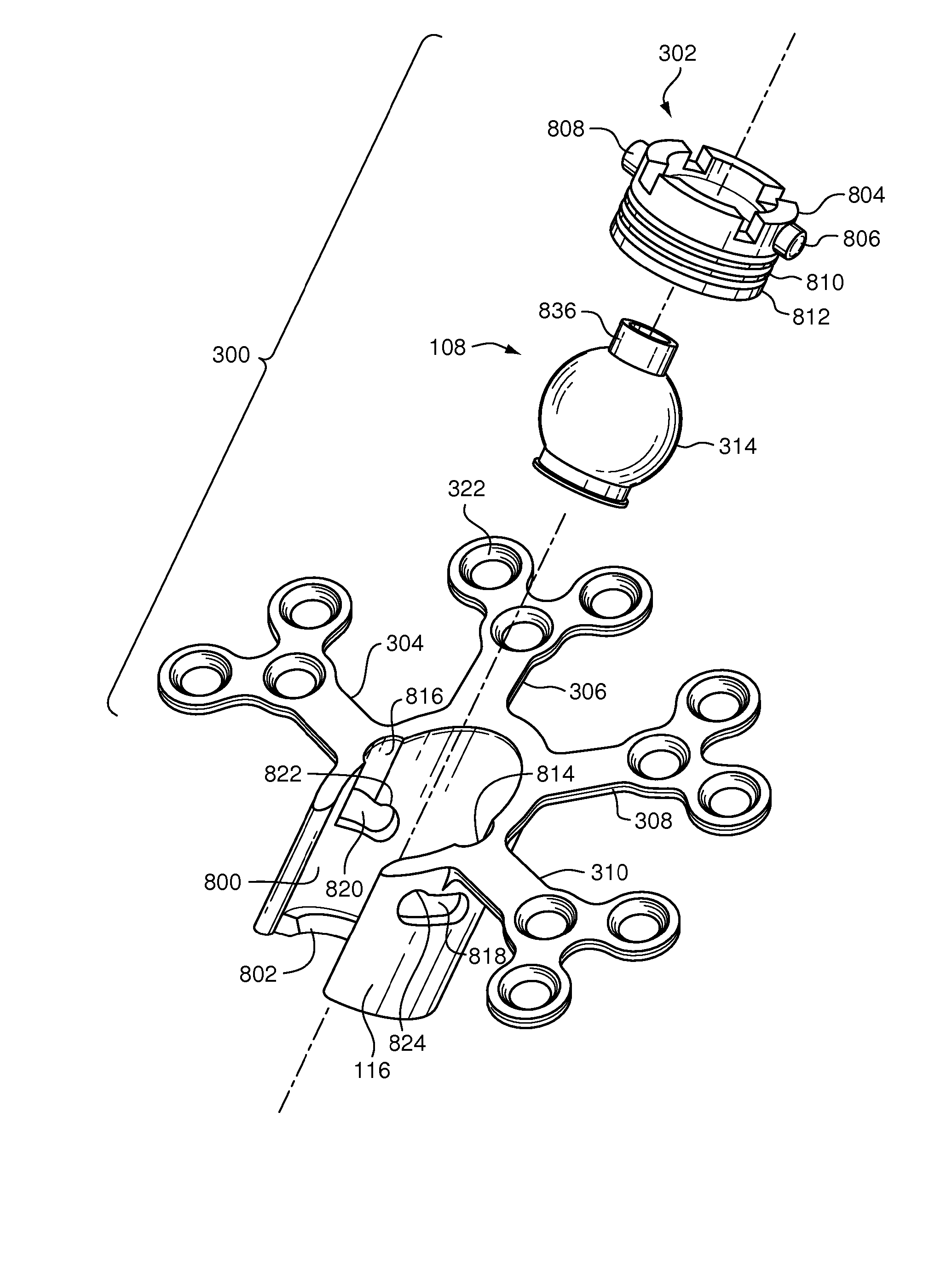
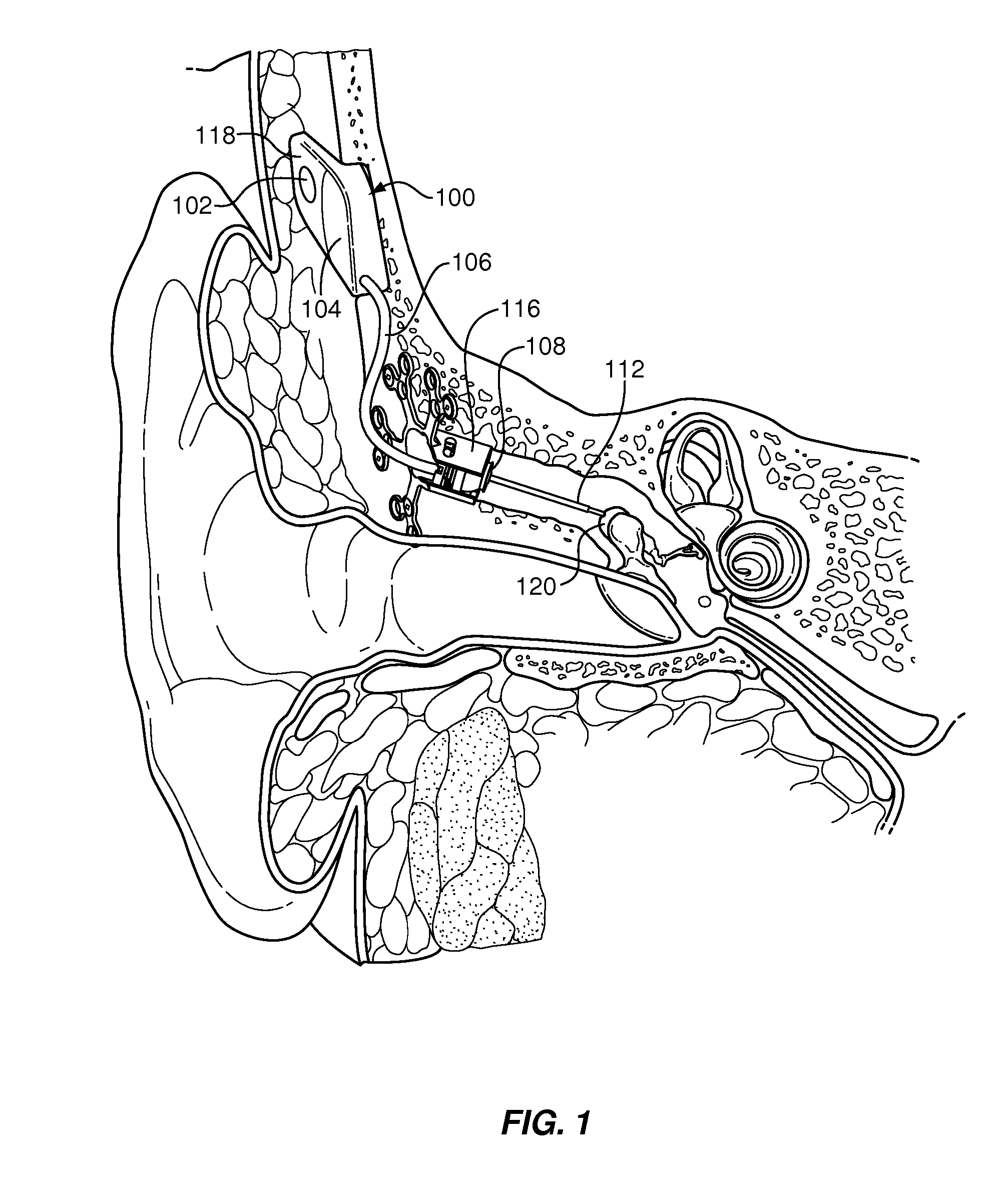
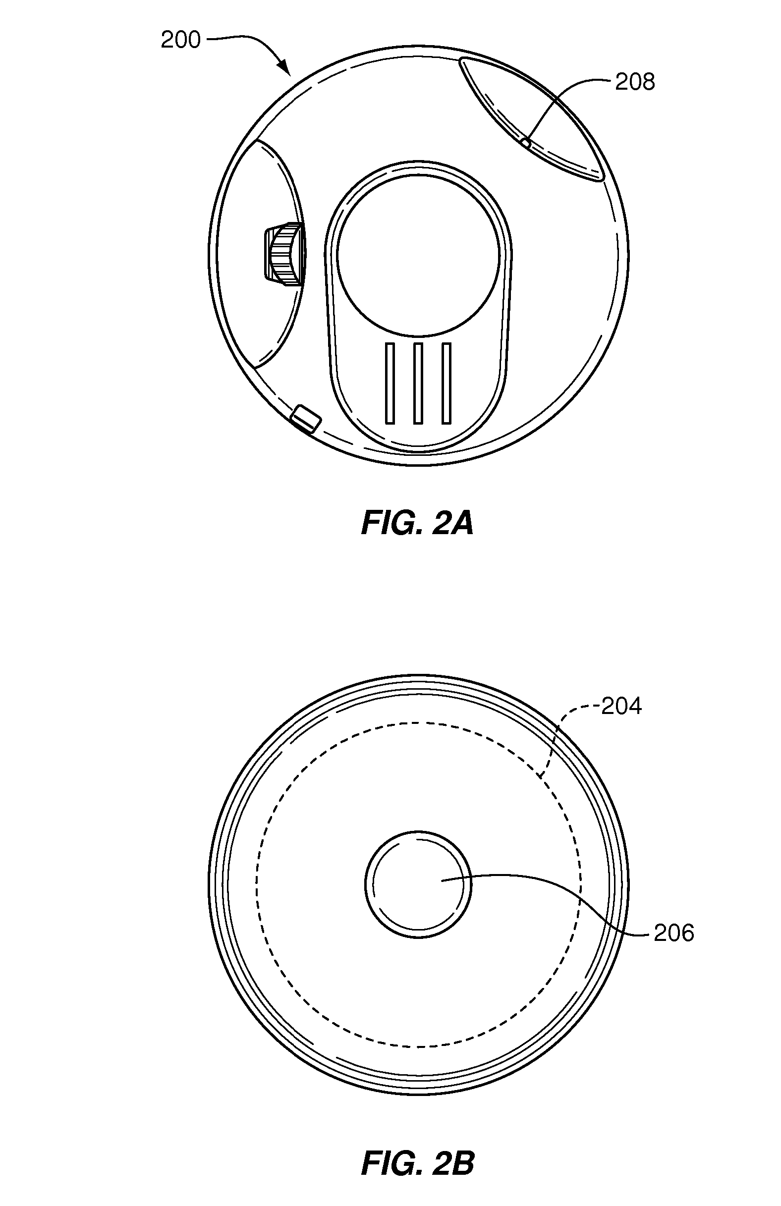
[0054]FIGS. 1, 2a, and 2b illustrate implantable and external componentry of a semi-implantable hearing aid system. The illustrated system includes implanted components shown in FIG. 1, and external components shown in FIGS. 2a and ...


PUM


Abstract

An implantable hearing aid transducer apparatus provides a simplified approach for interface with a middle ear component. The transducer includes a transducer housing, an actuator for middle ear coupling, and a driver having a magnet or coil interconnected to the actuator to induce movement in response to driver signals. In one feature, the actuator may be advanceable through an aperture of the housing independent from operation of the driver. In another feature, a portion of the transducer may be rotatable. In another feature, a retention apparatus may function to selectively secure a rotatable portion of the housing in a selected position. In an additional feature, a seal may be disposed around a driver component and connected to the actuator.

Description

RELATED APPLICATIONS [0001] This application claims priority as a continuation application of U.S. patent application Ser. No. 10 / 821,721, filed on Apr. 9, 2004 and further identified as Attorney Docket No. 45568-00457, and as a continuation-in-part application of U.S. patent application Ser. No. 10 / 351,699, filed on Jan. 27, 2003 and further identified as Attorney Docket No. 45568-00427, each of the foregoing applications being hereby incorporated by reference in its entirety.FIELD OF THE INVENTION [0002] The invention is related to the field of implantable hearing aids, and in particular, to a simplified implantable hearing aid transducer system. BACKGROUND OF THE INVENTION [0003] In the class of hearing aids generally referred to as implantable hearing aids, some or all of various hearing augmentation componentry is positioned subcutaneously on or within a patient's skull, typically at locations proximate the mastoid process. Implantable hearing aids may be generally divided into...

Claims


Application Information

Patent Timeline
Patent Type & Authority Applications(United States)
IPC IPC(8): H04R25/00H04R23/00
CPCH04R2225/67H04R25/606
Inventor SCHNEIDER, ROBERTMILLER, SCOTTANDREWS, TRAVIS
Owner COCHLEAR LIMITED
Why Eureka
Try Eureka