Safety device with trigger mechanism

a safety device and trigger mechanism technology, applied in the field of safety devices, can solve the problems of only being suitable for injecting fluid into a patient, not suitable for taking a sample from a patient, and the needle may pass on the infection

Inactive Publication Date: 2008-02-28
KPR U S LLC
View PDF99 Cites 20 Cited by
  • Summary
  • Abstract
  • Description
  • Claims
  • Application Information

AI Technical Summary

Benefits of technology

[0011] According to an aspect of the present disclosure, a medical safety device is provided. The medical safety device includes a needle hub having a needle supported thereon; and a safety shield operatively mounted on the needle hub. The safety shield includes a pair of spaced legs and a foot member. Each of the legs has a distal segment and a proximal segment, each of the proximal segments has a proximal end hingedly attached to the foot member and a distal end hingedly attached to the distal segment at a hinge member, and each proximal segment includes a camming surface. The safety shield further includes a trigger supported on the foot member. The trigger includes a camming member and is movable to move the camming member into engagement with the camming surfaces of the proximal segments to effect movement of the legs from a first position in which the distal ends of the distal segments shield a distal end of the needle to a second position in which the distal end of the needle is at least partially exposed. The trigger is removably secured to the foot member such that, in use, the trigger can be removed from the foot member to prevent movement of the legs from the first position to the second position.

Problems solved by technology

There is a known problem associated with hypodermic needles, which is that once a hypodermic needle has been used on a patient, it may be contaminated with an infection from the patient, and there is therefore a risk that the needle may pass on the infection if it is allowed to come into contact with another person.
There are a number of problems with a device of this type.
Firstly, this device is only suitable for injecting fluid into a patient and not for taking a sample from a patient because the retraction of the needle is activated once the plunger is fully pushed into the cylinder and not when it is partially withdrawn from the cylinder as would be the case after the taking of a sample.
Also, the person who is to give the injection must remove the plastic cap some time before the injection takes place, and from this moment on until the needle is retracted, the device is unsafe.
However, this is painful for the patient.
Also, the operator may simply omit to retract the needle for whatever reason, thus leaving the needle exposed and unsafe.
However, the needle will be unsafe for the duration of the time fuse period and can cause problems if, for example, the retraction is automatically activated during an injection.
This renders the cost of the device significantly more than a conventional needle and needle-luer combination (a needle-luer is a small member which is adapted to fit onto a syringe and into which the base of the needle is mounted).
Also, because the needle is mounted directly to the stem of the described safety device, a needle manufacturer would have to significantly alter its conventional manufacturing process for producing needle and needle-luer combinations to manufacture the described device.

Method used


Image

  • Safety device with trigger mechanism
  • Safety device with trigger mechanism
  • Safety device with trigger mechanism

Examples


Embodiment Construction

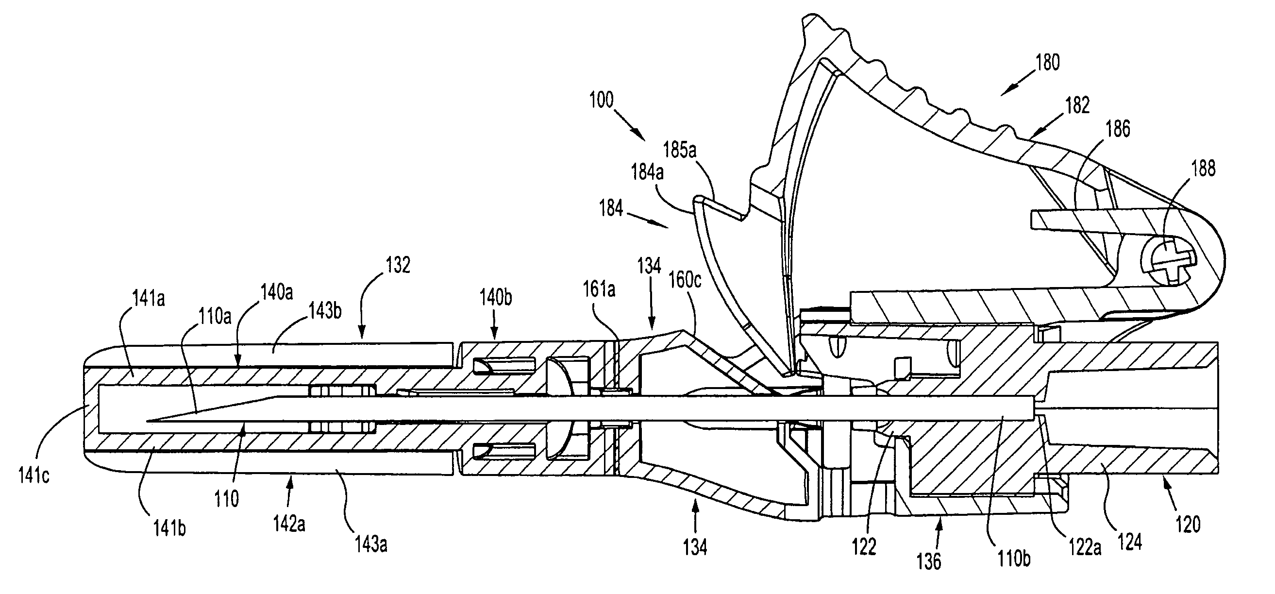
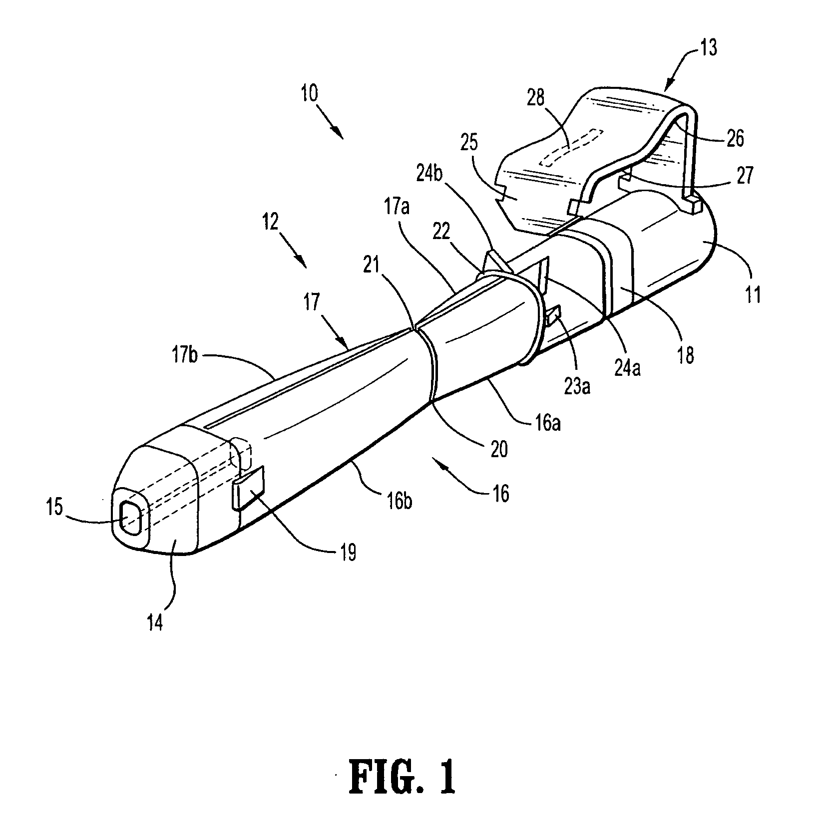
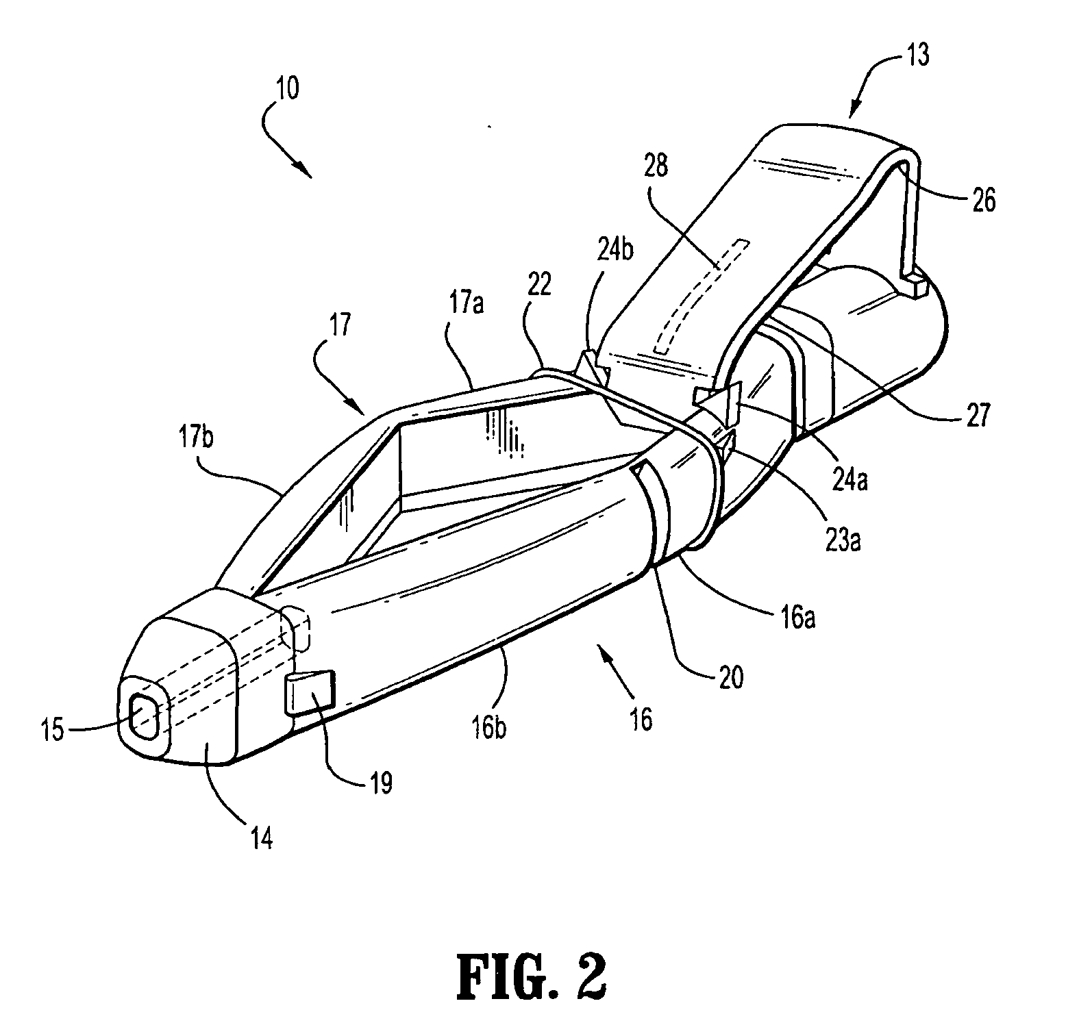
[0064] With reference to FIGS. 1 to 4 a safety device assembly 10 is presented comprising a needle receiving portion 11, a sheath portion 12 and a trigger mechanism 13.

[0065] The needle-receiving portion 11 operably receives and holds a needle (see FIGS. 3a, 3b, 3c) and / or a needle luer combination and assembly of such.

[0066] The sheath portion 12 comprises a nose plate 14 having a bore 15 therethrough, with resiliently flexible legs 16, 17 extending between the needle receiving portion 11 and the nose plate 14 and operably connected at these junctures by hinges 18, 19 on both legs 16, 17.

[0067] The safety device assembly 10 is formed by a one piece injection moulding process.

[0068] Each resiliently flexible leg 16, 17 of the safety device 10 has a central knee joint 20, 21 separating the back portion of the legs 16a, 17a and the front portion of the legs 16b, 17b. The configuration of the leg portions 16a, 17a; and knee joints 20, 21 ensure that longitudinal forces acting on th...


PUM


Abstract

A medical safety device is provided and includes a needle hub having a needle supported thereon; and a safety shield operatively mounted on the needle hub. The safety shield includes a pair of spaced legs and a foot member. Each proximal segment includes a camming surface. The safety shield further includes a trigger supported on the foot member. The trigger includes a camming member and is movable to move the camming member into engagement with the camming surfaces of the proximal segments to effect movement of the legs from a first position in which the distal ends of the distal segments shield a distal end of the needle to a second position in which the distal end of the needle is at least partially exposed. The trigger is removably secured to the foot member.

Description

CROSS-REFERENCE TO RELATED APPLICATIONS [0001] The present application is a Continuation-in-Part application which claims the benefit of and priority to U.S. application Ser. No. 10 / 716,771, filed on Nov. 19, 2003, which in turn claims the benefit of and priority to GB Application Serial No. 0303437.8, filed on Feb. 14, 2003, the entire content of each of which being incorporated herein by reference.BACKGROUND [0002] 1. Technical Field [0003] The present invention relates to safety devices and a method of manufacture thereof and, more particularly, to medical devices including hypodermic needles having a safety device provided therewith and methods of manufacturing the same. [0004] 2. Background of Related Art [0005] There is a known problem associated with hypodermic needles, which is that once a hypodermic needle has been used on a patient, it may be contaminated with an infection from the patient, and there is therefore a risk that the needle may pass on the infection if it is al...

Claims


Application Information

Patent Timeline
Patent Type & Authority Applications(United States)
IPC IPC(8): A61M5/32
CPCA61M5/326A61M2005/3267A61M2005/3247A61M5/3275
Inventor BEDFORD, ANTHONY JONATHANGALE, DAVID ROBERTCOCKER, ROBIN CRAIGCOOPER, ADRIAN EDWARD
Owner KPR U S LLC
Why Eureka
Try Eureka