
Fan and motor used thereto

a technology of motors and fans, applied in the direction of windings, mechanical energy handling, magnetic circuit shapes/forms/construction, etc., can solve the problems of considerable heat generation of coils in electronic devices, and considerable heat generation of coils

Active Publication Date: 2008-03-06
NIPPON DENSAN CORP
View PDF7 Cites 39 Cited by
  • Summary
  • Abstract
  • Description
  • Claims
  • Application Information

AI Technical Summary

Benefits of technology

[0005]In order to overcome the problems described above, preferred embodiments of the present invention provide a motor which may be used for a fan.

Problems solved by technology

In such a motor, however, a large electric current flows into a coil of an armature of the motor, and the coil generates considerable heat.
In addition, with a recent advance of the electronic devices, a considerable heat is generated in a casing of the electronic device.
In such a motor, as stated above, a large electric current flows into a coil of the motor, and the coil generates considerable heat.

Method used


Image

  • Fan and motor used thereto
  • Fan and motor used thereto
  • Fan and motor used thereto

Examples


Embodiment Construction

[0018]Recently, the demand for the motor having the reduced axial height and outer dimension, as well as a capacity of rotating at high speed, is called for. In the motor having the reduced thickness and the small dimension, diameters and axial thicknesses of an armature and a rotor magnet is reduced, making the motor energy-inefficient. As a result, a large electric current flows into the coil of the motors generating considerable heat.

[0019]The heat may compromise reliability and endurance of the motor since a copper wire used for the coil has a temperature limit and the generated heat influences bearing life. Thus, the motor should be designed such that the heat generated by the coil does not exceed the temperature limit of the copper wire, or a technique to reduce the heat generated by the coil is demanded.

[0020]In order to decrease heat generated by the coil of the motor, the electric current flowing into the coil should be decreased. In order to decrease the electric current f...


PUM


Abstract

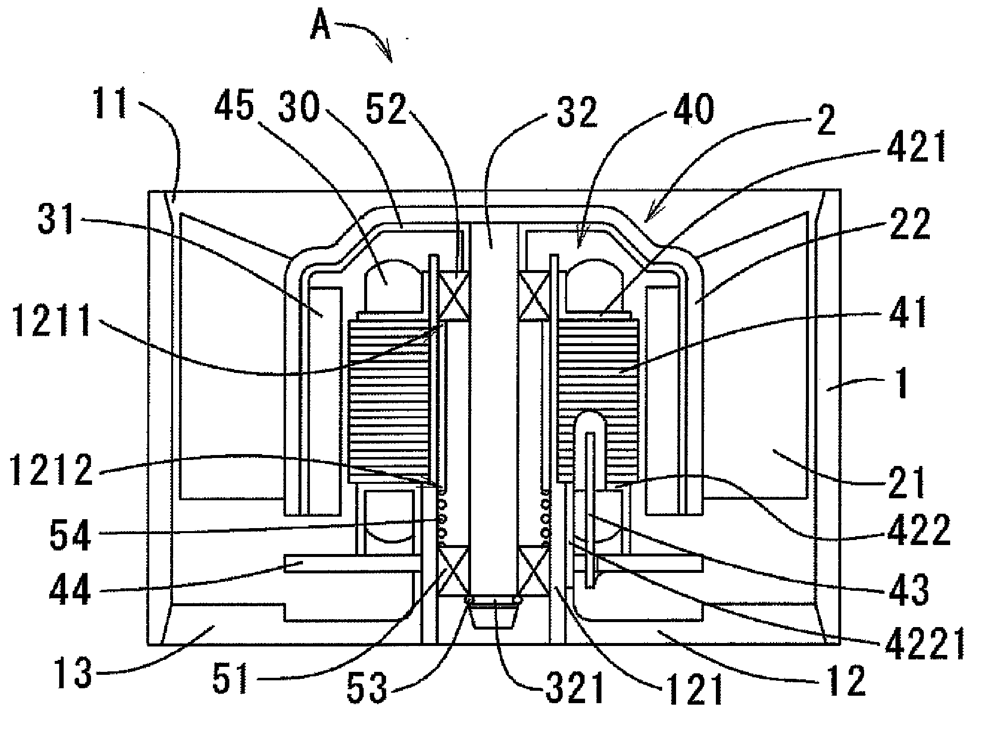
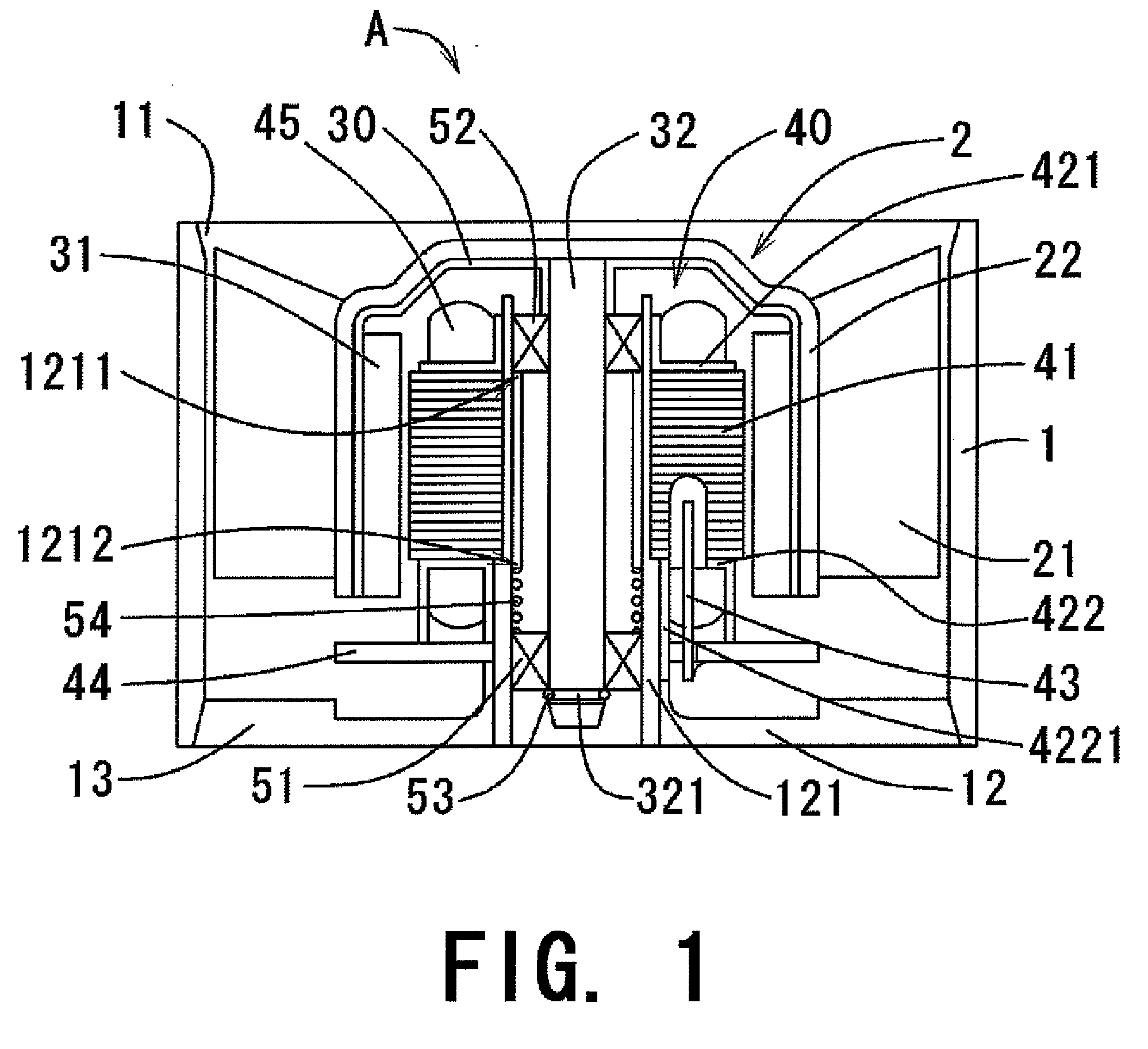
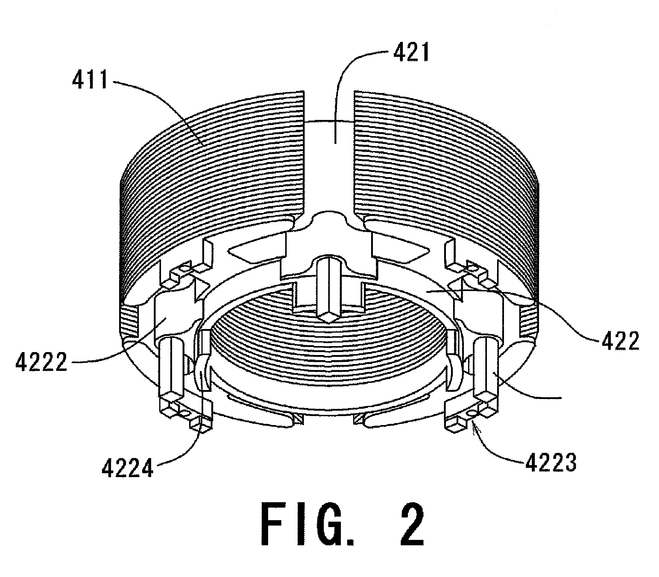
Axially upper and lower end surfaces of the stator core 41 are substantially covered by the first insulator 421 and the second insulators 422, both of which are made of resin. A boss 4222 is arranged circumferentially between the two neighboring teeth 411. In the preferred embodiment of the present invention, three bosses 4222 are arranged at three out of four positions defined between any two neighboring teeth 411. A conductor pin 43 is inserted into each boss 4222 along the axial direction. The boss 4222 includes a hole extending axially upward from the axially lower end thereof, in which a conductor pin 43 is fitted. An axially lower position of the conductor pin 43 axially downwardly protrudes from the boss 4222. Into each of the notched portions 441 arranged to the circuit board 44, the conductor pin 43 is inserted and is soldered with the circuit board 44 such that the conductor pin 43 and the circuit board are electrically connected.

Description

BACKGROUND OF THE PRESENT INVENTION[0001]1. Field of the Invention[0002]The present invention generally relates to a fan.[0003]2. Description of Related Art[0004]With numerous fans and drive motors for heat dissipation, disk drives, and like applications being installed in electronic devices, high speed motor operation is being demanded, in part because the demand for high speed data transfer and high heat dissipating capacity is increasing. A motor which rotates at a high speed is one answer to this need. In such a motor, however, a large electric current flows into a coil of an armature of the motor, and the coil generates considerable heat. In addition, with a recent advance of the electronic devices, a considerable heat is generated in a casing of the electronic device. In order to increase the heat dissipating capacity of a cooling fan, a motor used for the cooling fan rotates at high speed. In such a motor, as stated above, a large electric current flows into a coil of the mot...

Claims


Application Information

Patent Timeline
IPC IPC(8): H02K7/14H02K1/04
CPCH02K3/522H02K2203/03H02K21/22H02K7/14
Inventor YOSHIDA, YUSUKEMURAOKA, KOUJI
Owner NIPPON DENSAN CORP
Learn More