Handle for a riser card assembly

a technology of a riser card and a handle is applied in the direction of electrical apparatus casings/cabinets/drawers, coupling device connections, instruments, etc., which can solve the problems of limited backplane board size, insufficient space to add all of the desired components, and high extraction force often required

Inactive Publication Date: 2008-03-06
HON HAI PRECISION IND CO LTD
View PDF14 Cites 13 Cited by
  • Summary
  • Abstract
  • Description
  • Claims
  • Application Information

AI Technical Summary

Benefits of technology

[0006]A riser card assembly includes a bracket with a riser card secured therein, a handle, and a sliding mechanism. At least one expansion card is connected with the riser card and received in the bracket. The sliding mechanism slidably secures the handle to the bracket. The sliding mechanism includes at least one guiding pin formed on one of the handle and the bracket, and at least one slot receiving the guiding pin sliding therein defined in the other of the handle and the bracket. The at least one guiding pin slides in the at least one slot between a first position where the handle is in a retracted state to be together with the bracket, and a second position where the handle is in an extended state to be away from the bracket.

Problems solved by technology

However, the scale of the backplane board is limited, there is not enough space to add all of the desired components thereon.
While the riser card is firmly mounted on the backplane board, high extraction forces are often required to release the edge connector of the riser card from the slot of the backplane board.
Furthermore, the riser cards are often closely spaced together such that it is difficult to grip an individual riser card to pull it out of the slot.
However, the elongate lever may strike the backplane board, and cause damage.

Method used


Image

  • Handle for a riser card assembly
  • Handle for a riser card assembly
  • Handle for a riser card assembly

Examples


Embodiment Construction

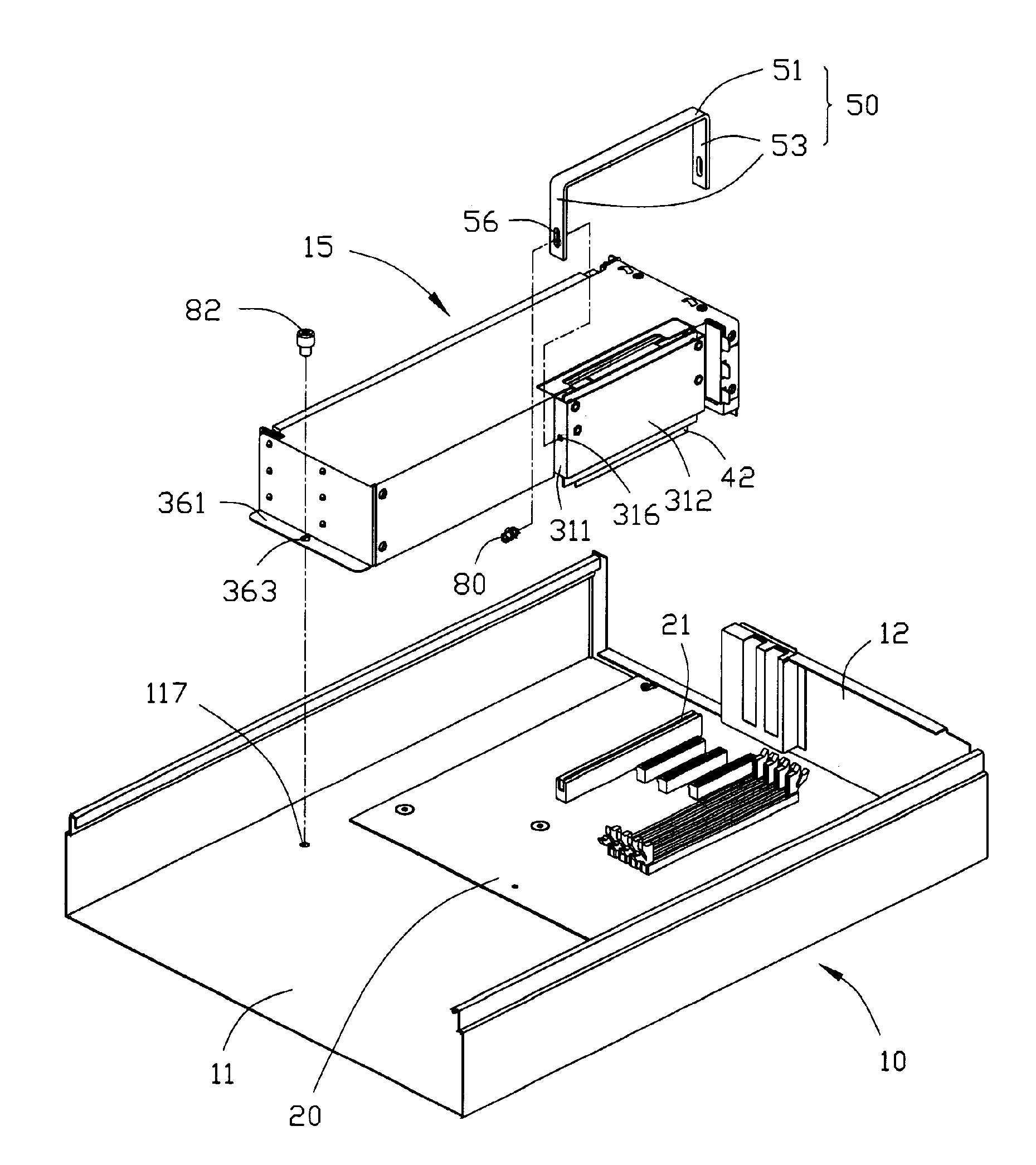
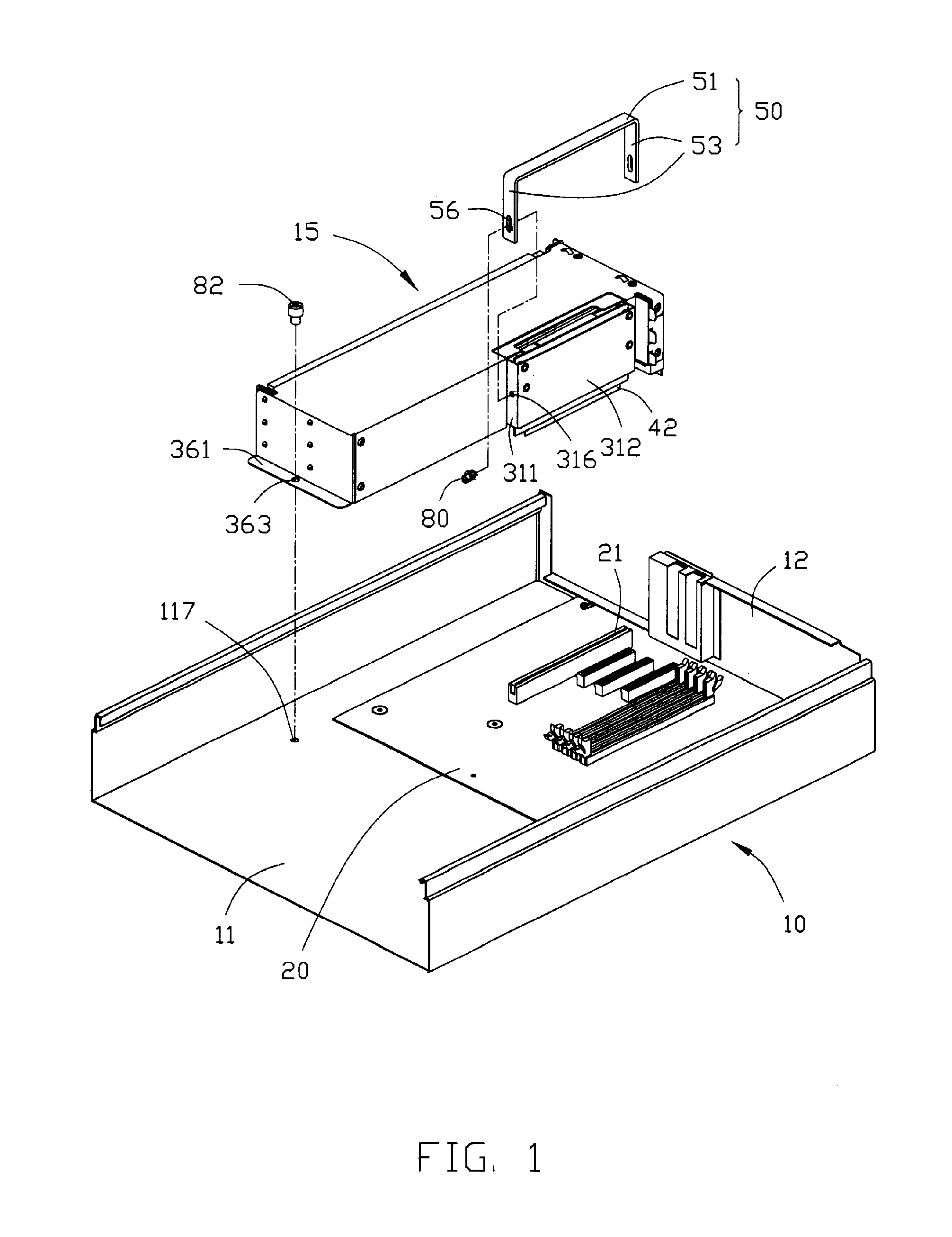
[0012]Referring to FIGS. 1 and 2, a handle 50 of a riser card assembly 15 in accordance with a preferred embodiment of the present invention is used to disengage the riser card assembly 15 from a motherboard 20 which is received in a chassis 10.

[0013]The chassis 10 includes a bottom plate 11. One edge of the bottom plate 111 extends upwardly and perpendicularly to form a side plate 12. The motherboard 20 is secured on the bottom plate 11. A screw hole 117 is defined in the bottom plate 11 near the motherboard 20. The motherboard 20 defines a plurality of expansion slots 21 for connecting different components.

[0014]The riser card assembly 15 includes a bracket 30, a riser card 40, and an expansion card 70. The expansion card 70 defines a plurality of holes 71 in two edges thereof.

[0015]The bracket 30 includes a rear board 31. One portion of the rear board 31 is stamped outwardly to form two lateral plates 311 and a securing plate 312 connecting the two lateral plates 311. The securin...


PUM


Abstract

A riser card assembly includes a bracket with a riser card secured therein, a handle, and a sliding mechanism. At least one expansion card is connected with the riser card and received in the bracket. The sliding mechanism slidably secures the handle to the bracket. The sliding mechanism includes at least one guiding pin formed on one of the handle and the bracket, and at least one slot receiving the guiding pin sliding therein defined in the other of the handle and the bracket. The at least one guiding pin slides in the at least one slot between a first position where the handle is in a retracted state to be together with the bracket, and a second position where the handle is in an extended state to be away from the bracket.

Description

1. FIELD OF THE INVENTION[0001]The present invention relates to handle mechanisms, and more particularly to a handle for disengaging a riser card assembly from a backplane board.2. DESCRIPTION OF RELATED ART[0002]With the development of computer technology, computer systems become more and more extensible, and different functions may be enhanced by adding different peripheral components, most of which are mounted on the backplane board. However, the scale of the backplane board is limited, there is not enough space to add all of the desired components thereon.[0003]As a result, riser cards are provided for connecting several peripheral components to the backplane board without occupying too much space. The riser card includes an edge connector connected to a slot of the backplane board and several slots connected to different peripheral components. While the riser card is firmly mounted on the backplane board, high extraction forces are often required to release the edge connector o...

Claims


Application Information

Patent Timeline
Patent Type & Authority Applications(United States)
IPC IPC(8): H05K7/14H05K7/18
CPCG06F1/185
Inventor FAN, CHEN-LUCHEN, LI-PING
Owner HON HAI PRECISION IND CO LTD
Why Eureka
Try Eureka