
Surgical instrument actuator

a technology of surgical instruments and actuators, applied in the field of surgical instruments, can solve the problems of unfavorable wrist movement of wrist mechanism, unfavorable wrist assembly of cables,

Active Publication Date: 2008-03-06
INTUITIVE SURGICAL OPERATIONS INC
View PDF21 Cites 146 Cited by
  • Summary
  • Abstract
  • Description
  • Claims
  • Application Information

AI Technical Summary

Benefits of technology

The invention is a surgical instrument that reduces the impact of actuation forces on the distal end of the instrument body, which is the part that comes into contact with the patient during surgery. This is achieved by applying a force to the drive element housing, which is opposite to the force applied to the drive element. This counteraction stabilizes the distal end component, minimizing or eliminating actuation forces at the joint. This design reduces the risk of injury to the patient and improves the precision of the surgery.

Problems solved by technology

Because the cables controlling the end effector must first pass through the wrist assembly in order to reach the end effector, these cables may undesirably apply forces to the wrist assembly.
In such situations, for example, a quick reduction in a force used to operate an end effector may cause the wrist mechanism to move, which is undesirable.

Method used


Image

  • Surgical instrument actuator
  • Surgical instrument actuator
  • Surgical instrument actuator

Examples


Embodiment Construction

[0058] In the following description, reference is made to the accompanying drawings, which illustrate several embodiments of the present invention. It is understood that other embodiments may be utilized, and mechanical compositional, structural, electrical, and operational changes may be made without departing from the spirit and scope of the present disclosure. The following detailed description is not to be taken in a limiting sense, and the scope of the embodiments of the present invention is defined only by the claims of the issued patent.

[0059] The terminology used herein is for the purpose of describing particular embodiments only and is not intended to be limiting of the invention. Spatially relative terms, such as “beneath”, “below”, “lower”, “above”, “upper”, and the like may be used herein for ease of description to describe one element's or feature's relationship to another element(s) or feature(s) as illustrated in the figures. It will be understood that the spatially ...


PUM


Abstract

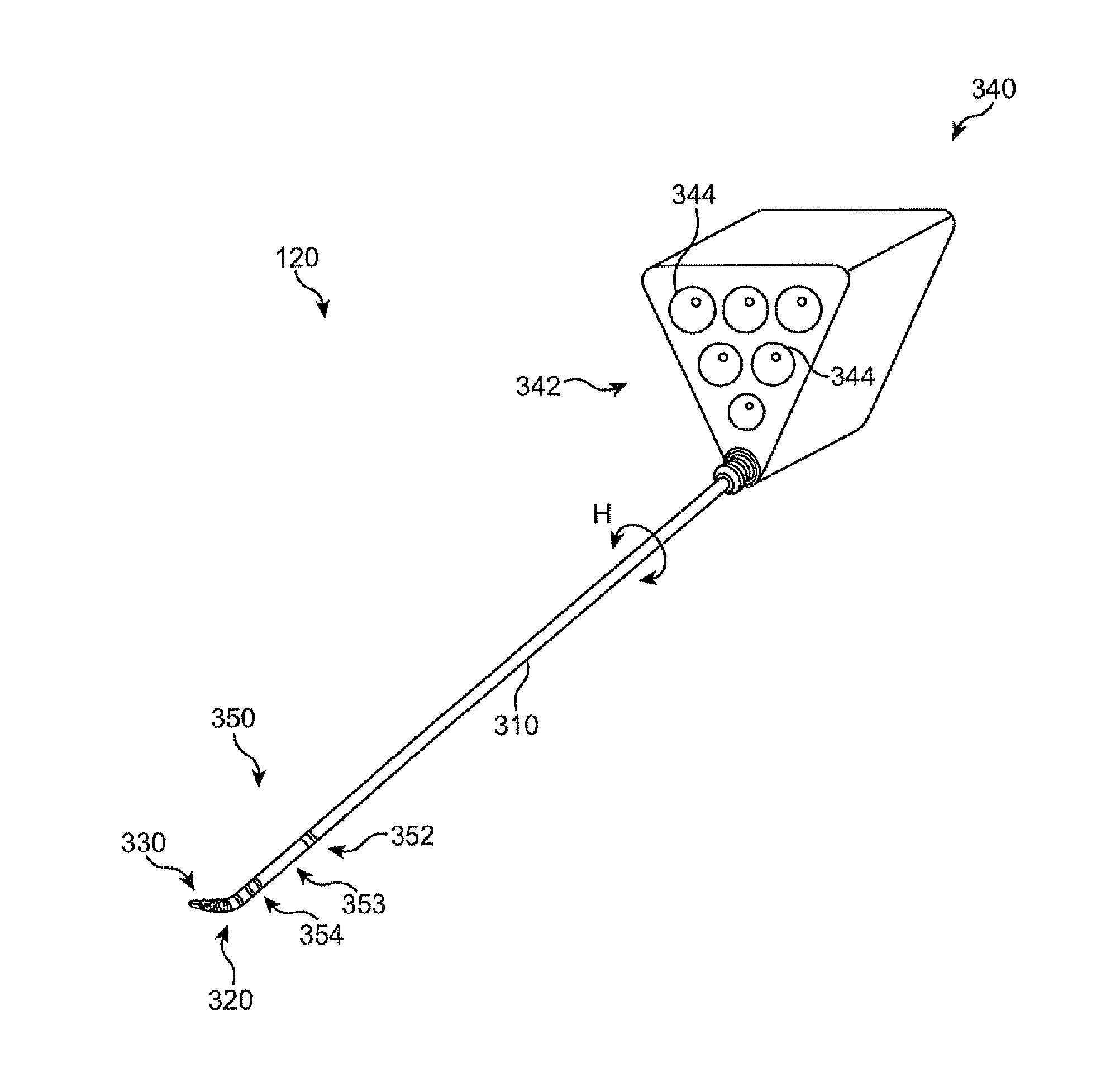
A surgical instrument body has a proximal portion, a distal portion, and a joint between the proximal and distal instrument body portions. A drive element housing extends through the proximal and distal instrument body portions and through the joint. A force to actuate a component at the distal end of the instrument body is applied to the drive element. A second force in the opposite direction is applied to the drive element housing, and this second force is also applied to the component. The opposite direction forces stabilize the component so that when the distal component is actuated, the actuation does not significantly affect the joint position.

Description

CROSS REFERENCE TO RELATED APPLICATIONS [0001] This application claims the benefit of priority from U.S. Provisional Patent Application No. 60 / 813,129, filed 13 Jun. 2006, entitled “Minimum Net Force Actuation,” the disclosure of which is incorporated by reference herein in its entirety. [0002] This application is related to, and incorporates by reference in its entirety, concurrently filed U.S. patent application Ser. No. ______ [Atty. Docket No. ISRG 00580] entitled “Surgical Instrument Actuation System” by Thomas G. Cooper and Matthew R. Williams. [0003] In addition, this application is related to the following concurrently filed United States patent applications, all of which are incorporated by reference. [0004] U.S. patent application Ser. No. ______ [Atty Docket No. 00500] entitled “Retraction of tissue for single port entry, robotically assisted medical procedures” by Mohr; [0005] U.S. patent application Ser. No. ______ [Atty Docket No. 00501] entitled “Bracing of bundled me...

Claims


Application Information

Patent Timeline
Patent Type & Authority Applications(United States)
IPC IPC(8): A61B17/29
CPCA61B19/201A61B19/22A61B19/2203A61B2017/003A61B2017/00314A61B2017/2902A61B2017/00477A61B2017/2927A61B2017/2929A61B2019/2234A61B2019/2238A61B2019/2242A61B2019/2246A61B2017/2905A61B34/30A61B34/70A61B34/71A61B90/11A61B2034/305A61B2034/306A61B2034/715
Inventor COOPER, THOMAS G.WILLIAMS, MATTHEW R.
Owner INTUITIVE SURGICAL OPERATIONS INC
Learn More