Corner joint for pultruded window frame

a window frame and corner joint technology, applied in the direction of dovetail-like connections, rod connections, ropes and cables for vehicles/pulleys, etc., can solve the problems of difficult forming corners which need to be mechanically fastened using corners, relatively slow and more expensive process, and the practice of not being widely adopted, etc., to achieve constant spacing and not constant spacing

Inactive Publication Date: 2008-03-13
OMNIGLASS
View PDF11 Cites 8 Cited by
  • Summary
  • Abstract
  • Description
  • Claims
  • Application Information

AI Technical Summary

Benefits of technology

[0023]Preferably the first portion of each surface of the first leg portion is shaped so that it has a substantially constant spacing from the corresponding surface of the first lineal from the corner up to the tapered second portion. However a light taper may be provided so that the spacing is not constant. The best adhesive effect is of course obtained where the spacing is constant and selected to provide a sufficient narrow gap that the adhesive can work as a film with little or no shearing forces.

Problems solved by technology

One long standing problem with the manufacture of window or door frames from pultruded fiber reinforced resin materials has been the difficulty of forming corners which need to be mechanically fastened using corner inserts, in comparison with the major competitor of extruded vinyl where the corners can be quickly and inexpensively welded.
This is a relatively slow and more expensive process which is perceived to be a significant disadvantage relative to vinyl.
However this injection is itself problematic so that the practice has not been adopted widely.

Method used


Image

  • Corner joint for pultruded window frame
  • Corner joint for pultruded window frame
  • Corner joint for pultruded window frame

Examples


Embodiment Construction

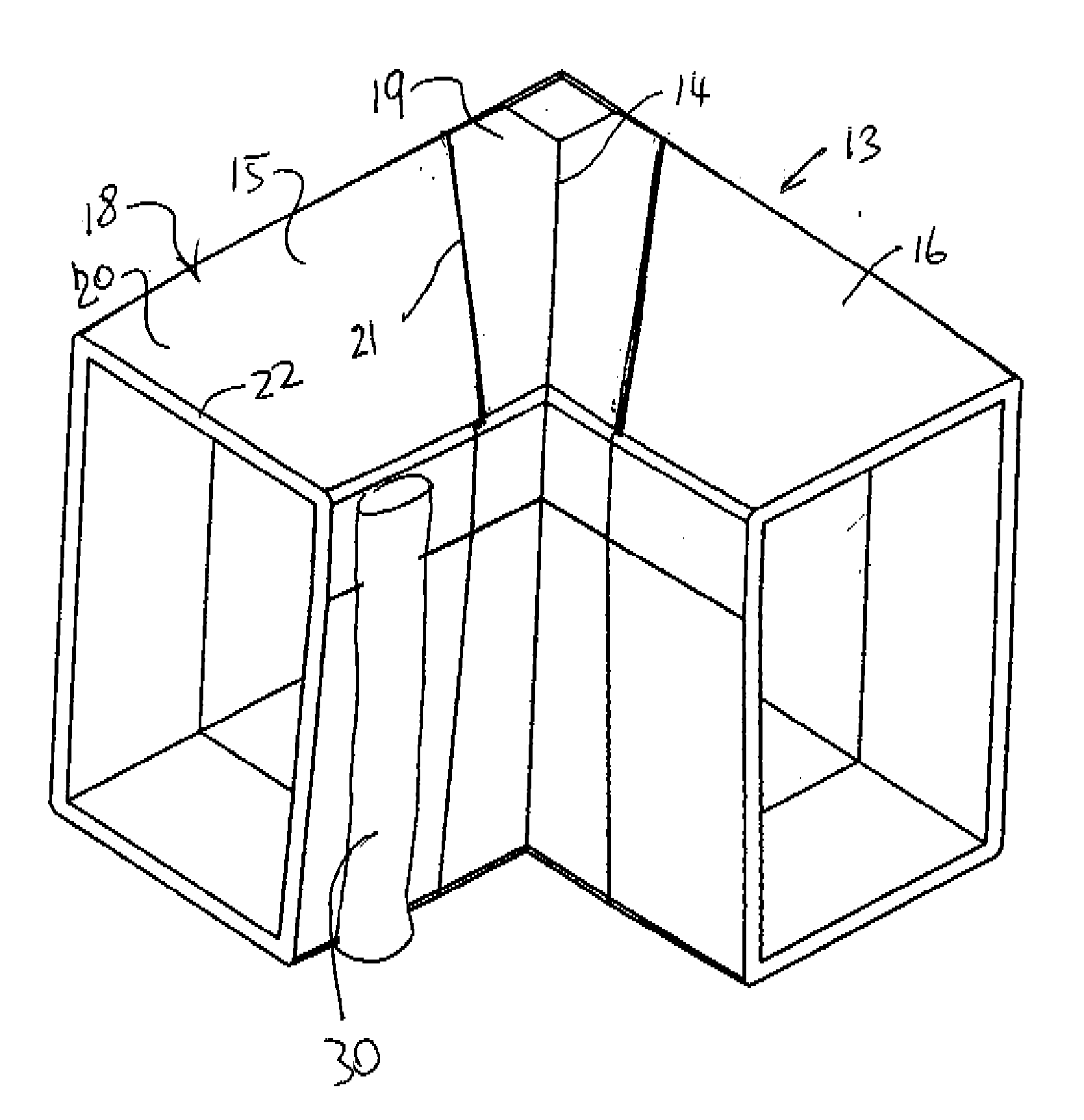
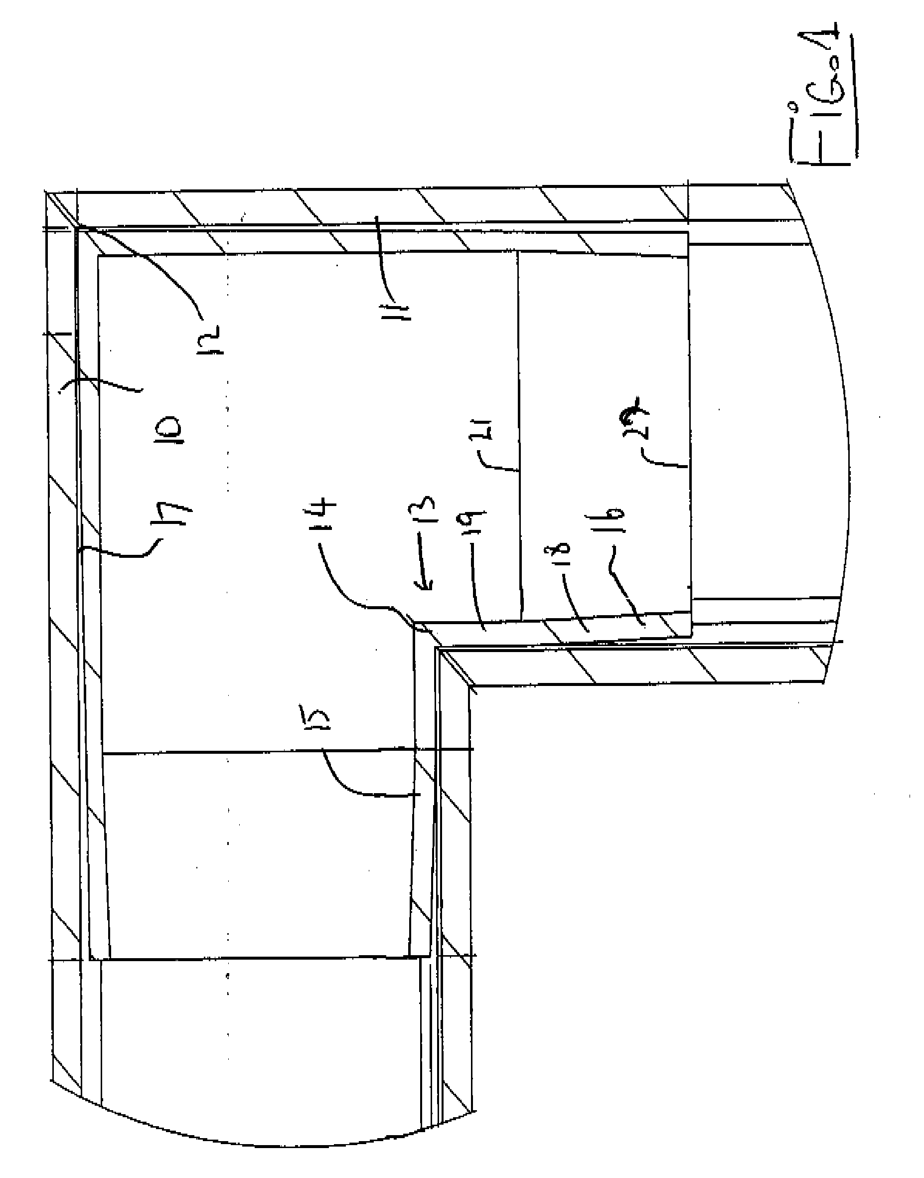
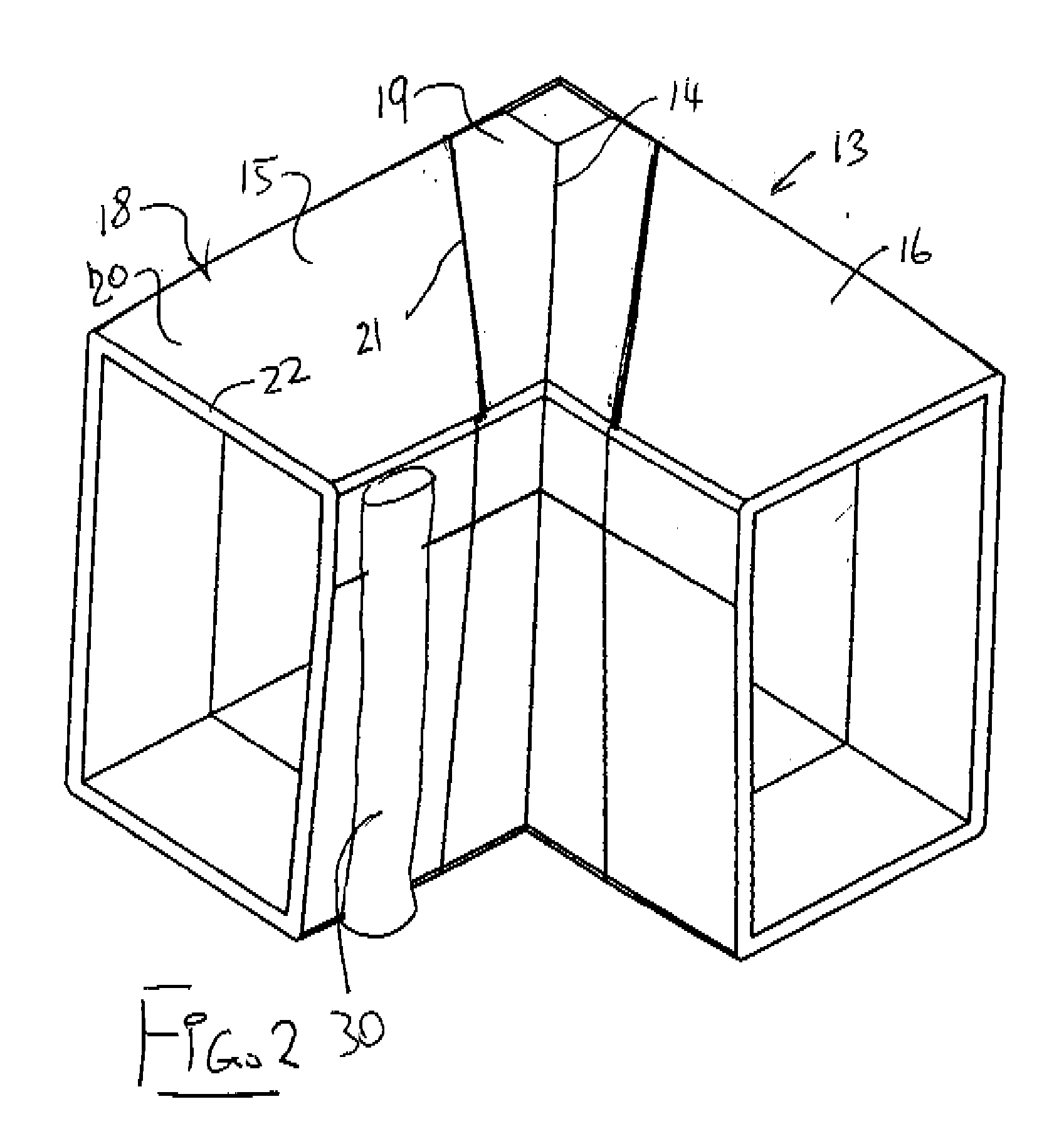
[0046]In FIG. 1 is shown a joint at a corner of a frame for a window or similar pultruded frame. The frame includes two frame lineals indicated at 10 and 11 respectively which connect together at a mitre joint 12.

[0047]The frame members 10 and 11 are formed by pultrusion by a fiber reinforced resin material so that they provide a constant cross section along the length of the frame members. The frame members are cut to length from a continuous pultruded lineal and can be connected at the corners by cutting the corners at an angle to provide a mitre joint or by connecting the corners at a butt joint. The corner as shown is at 90° so that the frame member 10 is at 90° to the frame member 11 but it is not essential that the corners be at right angles.

[0048]The corner connection is formed by providing a corner insert member generally indicated at 13. This corner insert member is formed as an injected moulded plastics part which defines an integral member defining a coupling portion 14 a...


PUM


Abstract

A corner joint between two frame lineals of a pultruded window frame is defined by inserting a leg of a corner member into a hollow interior of each lineal and attaching the legs to the lineals by adhesive. Each leg has a plurality of surfaces thereof each having a first portion at the corner which lies closely adjacent a corresponding surface of the first lineal and a second portion, at the end of the first portion remote from the corner which tapers inwardly away from the corresponding surface of the first lineal such that a spacing therebetween increases in the direction away from the corner. The adhesive is applied to the tapered portion and the taper acts to force the adhesive along the leg to the first portion and to the ends of the lineals where the excess can be wiped away.

Description

[0001]This invention relates to a method of forming a corner joint for a window or door frame which is particularly applicable to materials such as fiber reinforced resin which cannot be welded.BACKGROUND OF THE INVENTION[0002]One long standing problem with the manufacture of window or door frames from pultruded fiber reinforced resin materials has been the difficulty of forming corners which need to be mechanically fastened using corner inserts, in comparison with the major competitor of extruded vinyl where the corners can be quickly and inexpensively welded.[0003]Typically corners for pultruded materials are formed using an injection molded corner member which has two legs one of which slides into each lineal at the corner and is fastened in place by screws inserted through the wall of the lineal into a screw receptacle in the corner member. This is a relatively slow and more expensive process which is perceived to be a significant disadvantage relative to vinyl.[0004]It is known...

Claims


Application Information

Patent Timeline
Patent Type & Authority Applications(United States)
IPC IPC(8): E06B1/04
CPCE06B3/9682Y10T403/4665Y10T403/4602Y10T403/635Y10T403/4694Y10T403/76Y10T403/7024F16B2200/10F16B2200/20F16B2200/30
Inventor DAVIES, LAURENCE W.
Owner OMNIGLASS
Why Eureka
Try Eureka