Fishing accessory, in particular a line cutter

a line cutter and accessory technology, applied in fishing, other angling devices, animal husbandry, etc., can solve the problems of inconvenient use, inconvenient manufacture, and inability to meet the needs of users, so as to avoid any deformation of jamming and cutting zones, improve the retention of the line cutter, and limit the ability to slide.

Inactive Publication Date: 2008-06-24
DECATHLON SA
View PDF97 Cites 6 Cited by
  • Summary
  • Abstract
  • Description
  • Claims
  • Application Information

AI Technical Summary

Benefits of technology

[0007]In a variant embodiment, the jamming zone is also defined by an acute-angled cutout between the rear portion of the main body and the other longitudinal prong. This version is particularly suitable for fishing lines of the braided type which, when compared with monofilament type lines, are larger in diameter and less slippery.
[0010]In a variant embodiment, the longitudinal prongs are interconnected by at least one spacer which is curved to a circularly arcuate shape in the operation of stamping the plate to shape the accessory. The presence of the spacer enables the spacing between the two side prongs to be kept constant and thus avoid any deformation of the jamming and cutting zones while the accessory is being put into place on the body of the rod. The spacer also improves the retention of the line cutter on the body of the fishing rod while the longitudinal prongs are being bound, by limiting its ability to slide.

Problems solved by technology

That accessory nevertheless presents drawbacks.
This can be awkward for the user.
Manufacture is necessarily complex, requiring several parts to be made and then assembled together.

Method used


Image

  • Fishing accessory, in particular a line cutter
  • Fishing accessory, in particular a line cutter

Examples


first embodiment

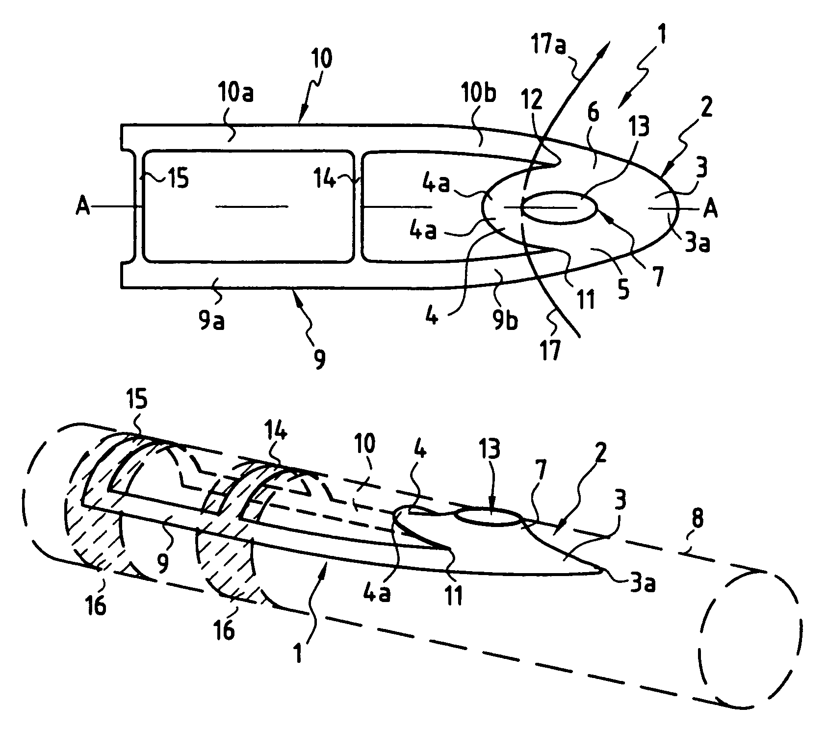
[0017]FIGS. 1 and 2 show the accessory 1 that is made by cutting out and stamping a thin metal sheet, e.g. of stainless steel and of the type having a thickness of 0.2 millimeters (mm). The stamping that takes place after cutting out serves to give the various portions constituting accessory 1 their three-dimensional shape.

[0018]More precisely, the accessory comprises firstly a main body 2 which is generally oval in overall shape, having a front portion 3, a rear portion 4, and two side portions 5 and 6, which portions surround a central portion 7. The main body 2 and also the accessory as a whole in this first embodiment, are symmetrical about a longitudinal plane A-A which, when the accessory 1 is put into place on the body 8 of the fishing rod, also corresponds to the longitudinal plane of said body.

[0019]The terms “front” and “rear” are used relative to the direction taken up by the accessory when it is in place on the body 8 of the fishing rod.

[0020]The accessory 1 also has two...

second embodiment

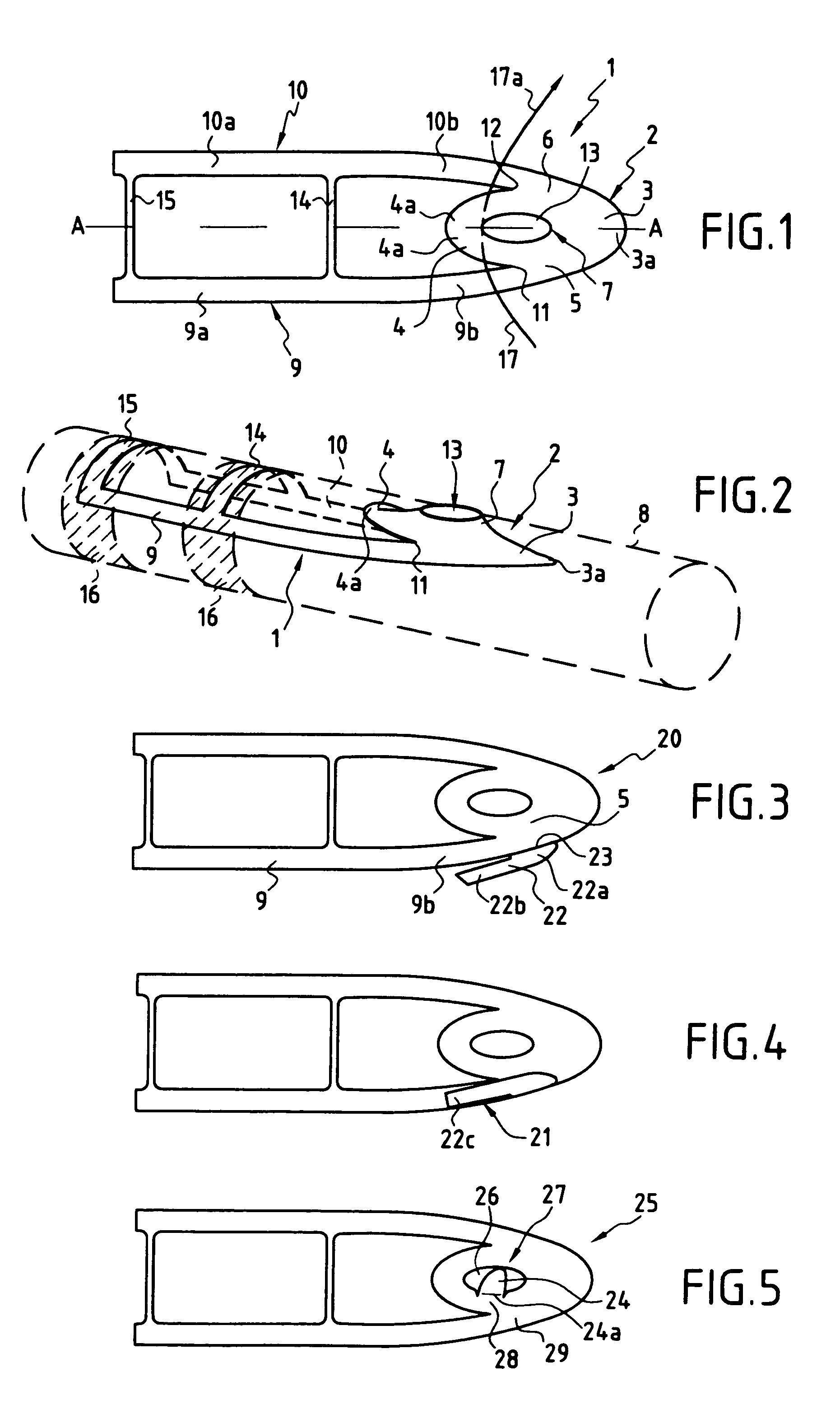
[0037]The second embodiment described below and shown in FIGS. 3 and 4 is more particularly adapted to smooth lines, in particular of the monofilament type, having a surface state that is more slippery and for which jamming requires contact over an area.

[0038]In this second embodiment, the accessory 20 differs from the accessory 1 of the first embodiment solely in the configuration of the jamming zone 21 which is now constituted by a zone extending between one of the longitudinal prongs 9 and a flap 22.

[0039]When the metal plate constituting the accessory 20 is cut out, a flap 22 is formed that constitutes a kind of projection from the curved portion 9b of the longitudinal prong 9 where it joins the side portion 5 of the main body 2.

[0040]As can be seen clearly in FIG. 3, the flap 22 has a front portion 22a which is thus connected to the side prong 9, and a rear portion 22b which is rectilinear and which is immediately adjacent to the longitudinal prong 9.

[0041]In order to make the ...

third embodiment

[0043]The third embodiment shown in FIG. 5 differs from the second only in the location of the flap 24. When cutting out the metal plate constituting the accessory 25, the flap 24 is constituted by a projection from a side portion of the main body towards the inside of the hole 26. As can be seen in FIG. 5, the flap 24 is connected to the side portion 28 via a fold line 24a.

[0044]To make the jamming zone, the metal plate is folded about the fold line 24a so as to bring said flap 24 down onto the top face of the longitudinal prong 29.


PUM


Abstract

The line cutter suitable for fitting to the body of a fishing rod is made as a single piece obtained by cutting out and stamping a metal plate. It comprises firstly a main body with a front portion, a rear portion, and two side portions, and secondly two longitudinal prongs extending the side portions of the main body rearwards. The plate is cut out and stamped in such a manner that, when the line cutter is mounted on the body of the fishing rod, the longitudinal prongs and at least the front portion of the main body are in contact with the body of the fishing rod, the rear portion of the main body being raised so as to allow the line to be pass thereunder, and in such a manner that between the rear portion of the main body and the longitudinal prongs, a cutout in the shape of an acute angle on one side defines a cutting zone, while on the other side there is provided a jamming zone for jamming the fishing line. The line cutter is secured to the body of the fishing rod by binding the longitudinal prongs to said body.

Description

[0001]The present invention relates to a fishing accessory suitable for fitting to the body of a fishing rod, in particular a fishing rod having a reel. The invention relates more particular to a fishing accessory suitable for being used to cut a fishing line, and possibly also for temporarily holding a fish hook.BACKGROUND OF THE INVENTION[0002]A line cutter suitable for fitting to the body of a fishing rod is known from U.S. Pat. No. 4,730,409. That accessory comprises a cutter blade that is sandwiched between two plates that are fixed to each other. One of the two plates is secured to an open semicylindrical part for enabling the accessory to be fitted on the body of the fishing rod by receiving it. Access to the cutter blade takes place via a notch formed in the two assembled-together plates. On either side of the notch, the plates are curved towards the inside of the notch, thereby enabling the fish hook to be held temporarily.[0003]That accessory nevertheless presents drawback...

Claims


Application Information

Patent Timeline
Patent Type & Authority Patents(United States)
IPC IPC(8): A01K97/06A01K87/00A01K97/00
CPCA01K87/007A01K97/00A01K97/06
Inventor ZWIERSKI, SEBASTIEN
Owner DECATHLON SA
Why Eureka
Try Eureka