Display rack

Inactive Publication Date: 2014-09-30
3G POLYMERS LLC
View PDF25 Cites 6 Cited by
  • Summary
  • Abstract
  • Description
  • Claims
  • Application Information

AI Technical Summary

Benefits of technology

This patent describes a display rack that can hold multiple display boxes, showcasing them to consumers without the need for constant adjustment. The rack features support members that offer stability for the display boxes, while also allowing for easy placement and replacement. The focused use of the rack reduces the time it takes to prepare the display space, resulting in cost savings for retailers. The technical effects of this patent include improved display efficiency, durability, and ease of use for retailers.

Problems solved by technology

Further, the box has edges that may cut a person's finger's when the product is removed from the box.
Movement of one box may also cause adjacent boxes to move thereby rendering the entire shelf unattractive to consumers.
As such, the sidewalls of the box tend to become worn as the product is dispensed.
Still further, the box uses a substantial amount of cardboard material which increases the overall cost of the box.

Method used


Image

  • Display rack
  • Display rack
  • Display rack

Examples


Embodiment Construction

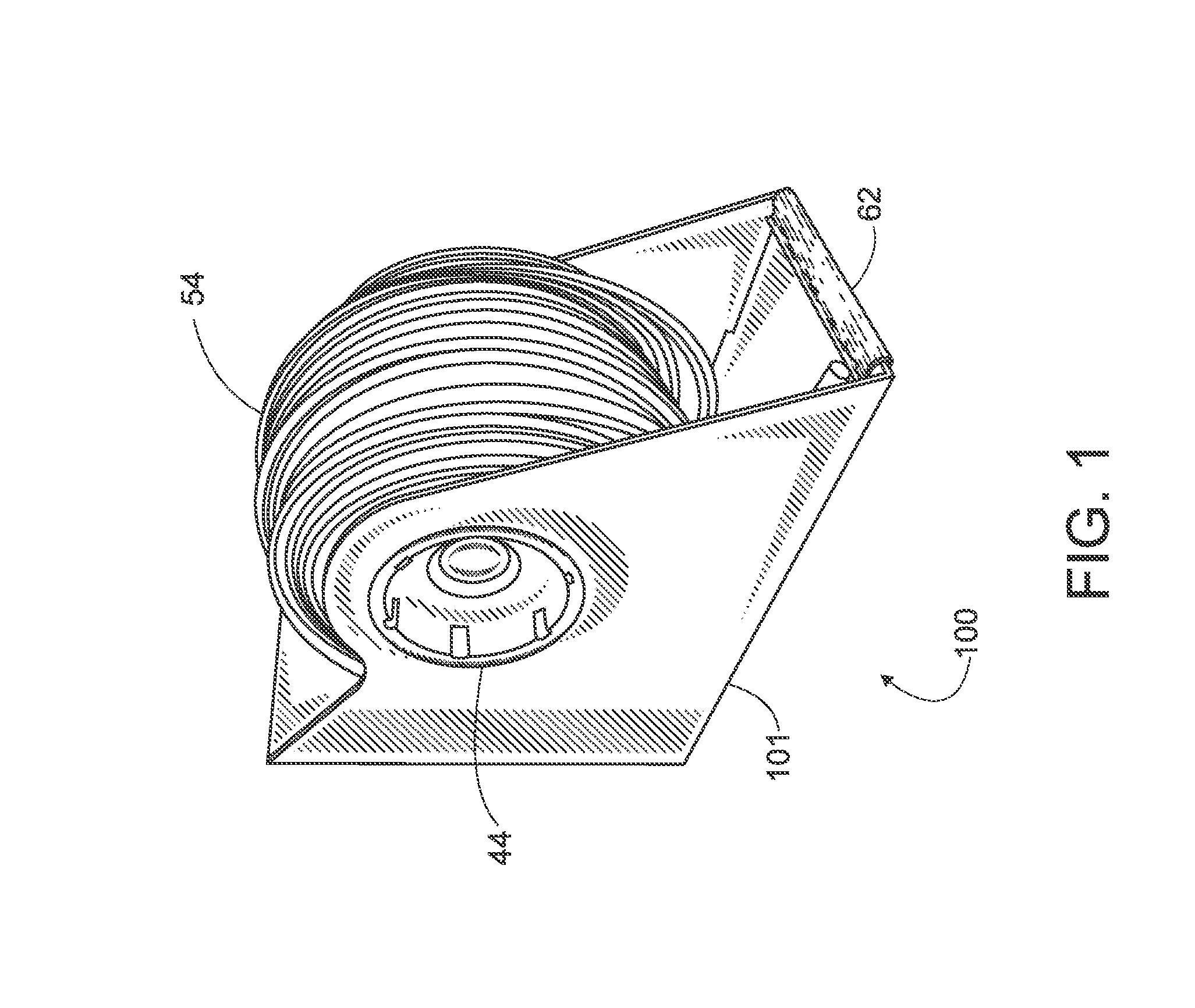
[0024]Referring to FIG. 1, the present invention is a display box or device 100 for storing, displaying, and dispensing articles such as flexible tubing 54 on a retail store self (not shown). Display box 100 generally comprises a one-piece housing 101, a spool assembly 44, flexible tubing 54 wound upon a spool assembly 44, and a bumper 62.

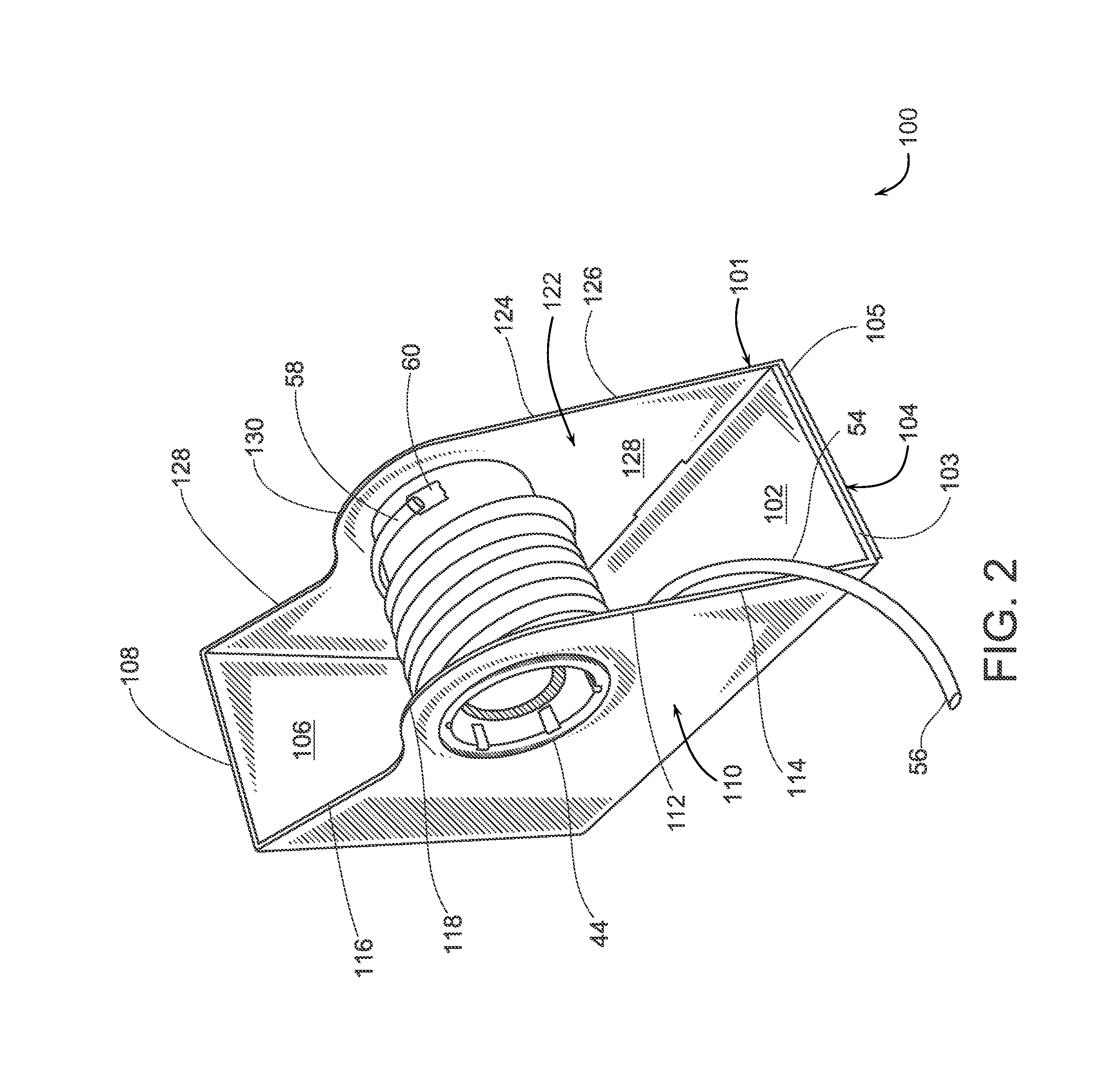
[0025]Referring to FIG. 2, one-piece housing 101 generally comprises an inner bottom wall 102, an outer bottom wall 104, a rear wall 106, a first side wall 110, a second side wall 122, and a rear wall 106. Inner and outer bottom walls 102 and 104 comprise a front edge 103 and a front edge 105, respectively. Rear wall 106 comprises an outside edge 108. First and second sidewalls 110 and 122 further comprise outside edges 112 and 124, respectively. First and second sidewalls 110 and 122 extend upward from inner and outer bottom walls 102 and 104, respectively, and are substantially perpendicular to rear wall 106. Outside edge 112 of first sidewall 11...


PUM

PropertyMeasurementUnit
Lengthaaaaaaaaaa
Flexibilityaaaaaaaaaa

Abstract

A display rack mountable on a shelf of a store for showcasing first and second display boxes and wound flexible tubing. The display rack comprises front and rear support members. The display rack further comprises first, second, and third open sidewall support members each having a first end engaged with the front support member and a second end engaged with the rear support member. The display rack further comprises a first stall formed between the first and second open sidewall support members. The first stall is adapted to receive the first display box. The display rack further comprises a second stall formed between the second and third open sidewall support members. The second stall is adapted to receive the second display box. The front and rear support members support the front and rear portions of the first and second display boxes, respectively.

Description

CROSS-REFERENCE TO RELATED APPLICATIONS[0001]This application claims priority to and is a continuation-in-part of application Ser. No. 12 / 964,809 filed on Dec. 10, 2010, now pending, which is a continuation-in-part of application Ser. No. 12 / 786,715 filed on May 25, 2010, now U.S. Pat. No. 8,210,464, both of which are hereby incorporated by reference in their entirety into this specification.BACKGROUND OF THE INVENTION[0002]U.S. Pat. No. 5,826,817 discloses a box for storing, displaying, and dispensing flexible tubing or other items that can be wound upon a spool such as ropes or chains. Such conventional boxes are mounted directly on a shelf of a retailer's store. Conventional boxes of this type have enjoyed wide commercial success but are not without drawbacks. For example, the product contained in the box is not substantially visible to the consumer. A consumer must look thru a window to determine what type of product is contained in the box. Further, the box has edges that may c...

Claims


Application Information

Patent Timeline
IPC IPC(8): A47F1/04A47F5/14A47F7/00A47G29/00A47B55/02A47B81/00A47F1/08A47F1/12A47F5/00A47F5/01A47F7/17B65D85/04B65H49/32
CPCA47F5/0025A47B81/007A47F5/01B65H49/322A47B55/02A47F1/121B65H49/00B65D85/04B65H49/321A47F1/082B65H2701/5112A47F7/17B65H2701/33B65H49/325A47F7/005A47F7/283
Inventor SELBY, WILLIAM, J.
Owner 3G POLYMERS LLC
Why Eureka
Try Eureka