Ventilating apparatus and method enabling a patient to talk with or without a trachostomy tube check valve

a technology of ventilating apparatus and patient, applied in the field of ventilating a patient, to achieve the effect of facilitating the patient's ability to speak

Active Publication Date: 2008-03-13
PHILIPS RS NORTH AMERICA LLC
View PDF16 Cites 99 Cited by
  • Summary
  • Abstract
  • Description
  • Claims
  • Application Information

AI Technical Summary

Benefits of technology

[0009]In an exemplary embodiment, the method comprises the steps of connecting the conduit with an exterior open end of an endotracheal tube positioned within a patient's trachea so that an interior open end leads into the patient's airway and lungs below the patient's vocal cords. The respiration assembly is repetitively cycles so that during the inhalation phase, the gas in the inhalation passage flows through the endotracheal tube and into the patient's airway and lungs, and during the exhalation phase, the exhalation valve is maintained relatively closed and the patient is allowed to exhale the gases in the patient's airway and lungs, passed the patient's vocal cords and out of the patient's mouth, thereby facilitating the patient's ability to speak. The pressure within at least one of the passages is monitored during both phases for purposes of determining the pressure within the patient's airway and lungs for use in operating the ventilator assembly.
[0012]The ventilator assembly is constructed and arranged to provide repetitive respiratory cycles, each including an inhalation phase during which the inhalation valve is relatively open and the exhalation valve is relatively closed and a flow of gas is allowed to pass through the inhalation passage and the endotracheal tube into the patient's airway and lungs. A controller is also provided for operating the inhalation valve and the exhalation valve, and the exhalation valve operates in a selected one of the following two exhalation phase modes: (1) a first mode wherein the exhalation valve is relatively open during the exhalation phase allowing the gas in the patient's airway and lungs after the preceding inhalation phase to pass through the open exhalation valve and an outlet of the ventilator assembly; and (2) a second mode wherein the exhalation valve is maintained relatively closed and the patient causes the gas in the patient's airway and lungs after the preceding inhalation phase to flow passed the patient's vocal cords and out of the patient's mouth, thus facilitating patient's ability to talk.
[0014]As indicated above, utilizing an endotracheal tube devoid of a check valve is an aspect of the present invention which secures the talking function without the known disadvantages of check valves. Nevertheless, another aspect of the present invention resides in providing a ventilating apparatus which overcomes many of the known disadvantages of the use of a check valve even though a check valve is present in the endotracheal tube.
[0016]The endotracheal tube has a check valve in the exterior open end thereof enabling the patient at the end of each inhalation phase to cause the gas in the patient's airway and lungs to pass through the patient's vocal cords and out of the patient's mouth, thus facilitating the patient's ability to speak, the check valve is operable to trap the pressure conditions within the passages at the end of the inhalation phase when both valves are relatively closed so as to allow the trapped pressure conditions in the passages at the end of each inhalation phase to equalize with the pressure conditions within the patient's airway and lungs during the exhalation phase. The ventilator assembly includes a pressure monitoring structure / assembly for monitoring the pressure conditions in the passages during both phases for purposes of determining the existing pressure conditions in the patient's airway and lungs for use in operating the ventilator assembly.

Problems solved by technology

However, there are disadvantages as well.

Method used


Image

  • Ventilating apparatus and method enabling a patient to talk with or without a trachostomy tube check valve
  • Ventilating apparatus and method enabling a patient to talk with or without a trachostomy tube check valve
  • Ventilating apparatus and method enabling a patient to talk with or without a trachostomy tube check valve

Examples


Embodiment Construction

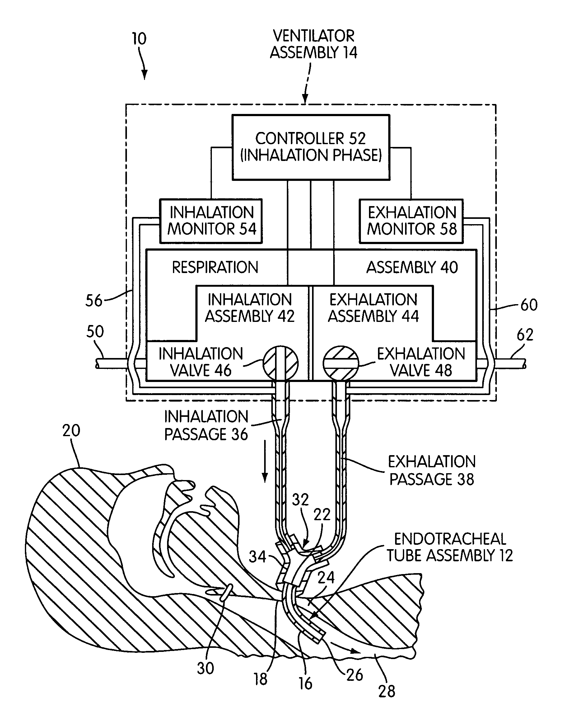
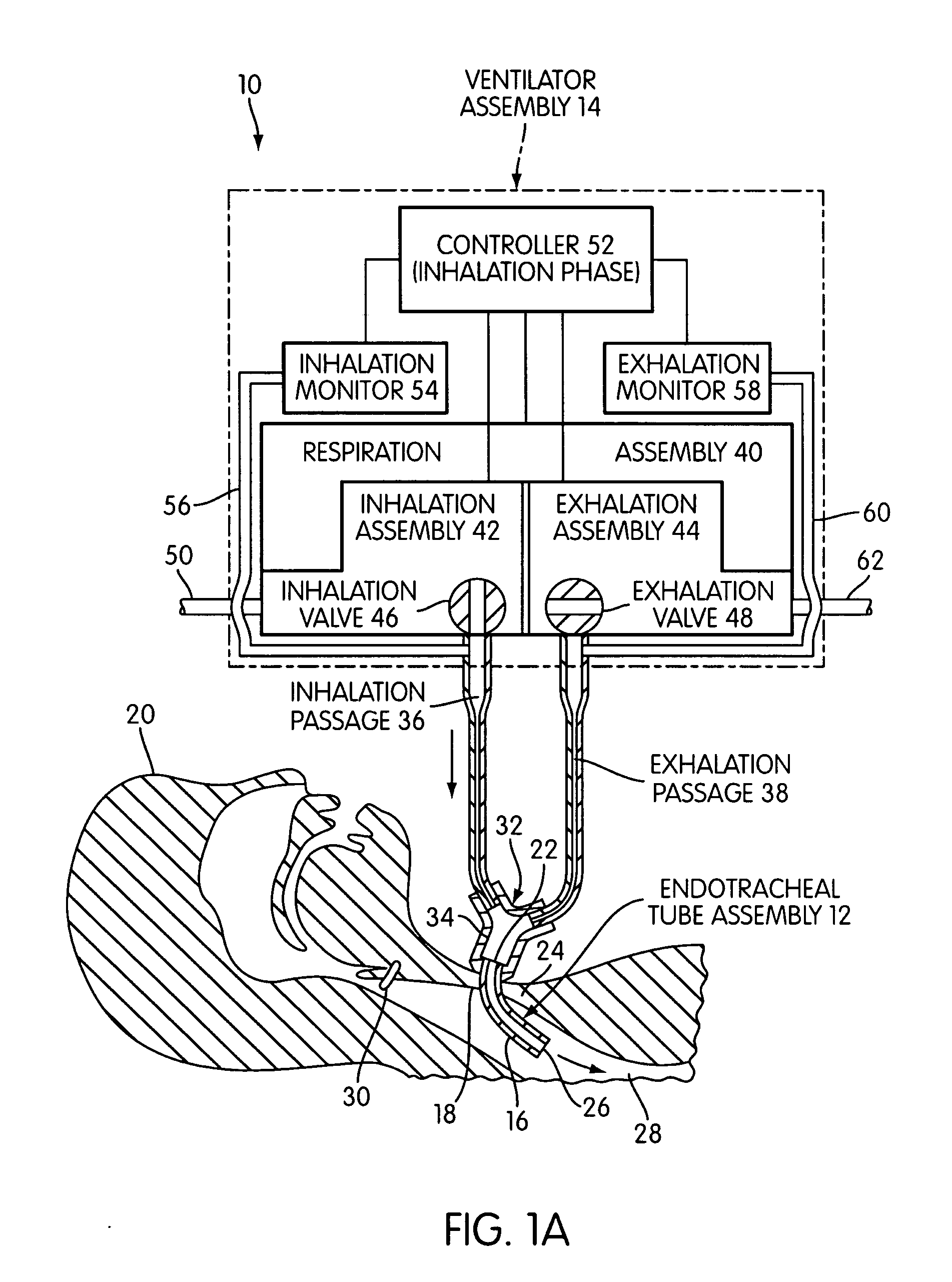
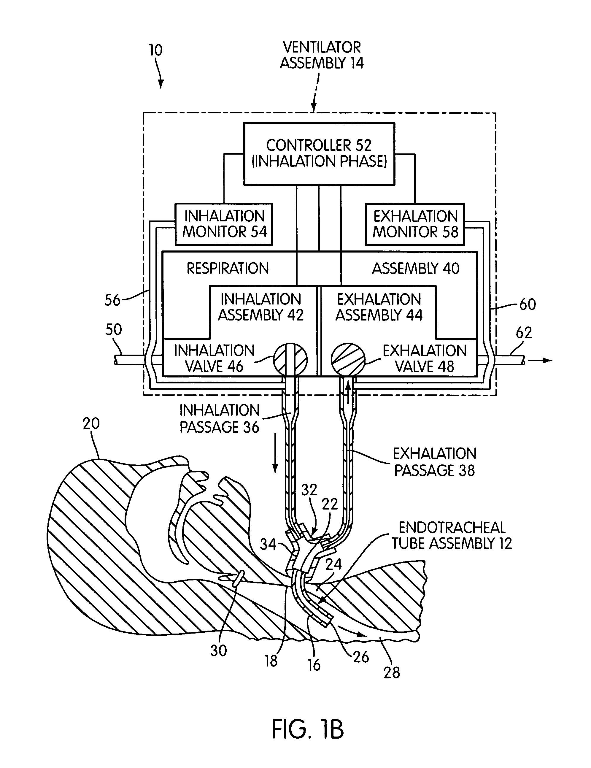
[0028]Referring now more particularly to FIGS. 1A, 1B, 2A, 2B, and 3 (or “FIGS. 1-3” for short) of the drawings, there is shown a ventilating apparatus, generally indicated at 10, embodying the principles of the present invention. Ventilating apparatus 10 includes, in general, an endotracheal tube assembly, generally indicated at 12, and a ventilator assembly, generally indicated at 14.

[0029]Endotracheal tube assembly 12 includes an endotracheal tube 16, constructed, for example, in accordance with the principles disclosed in the incorporated '356 patent. Endotracheal tube 16 is constructed and arranged to be mounted in a trachea 18 of a patient 20, as shown in FIGS. 1-3, so that an exterior open end 22 is suitably fixed in position exteriorly of the patient's neck 24 and an interior open end 26 communicates with the patient's airway and lungs 28 at a position below the patient's vocal cords 30.

[0030]In FIGS. 1-3, endotracheal tube 18 is shown as being devoid of a check valve, often...


PUM


Abstract

A method of operating a ventilator assembly having inhalation and exhalation passages communicating with one another, and a respiration assembly that can perform repetitive respiratory cycles. The method includes (a) connecting the conduit with an open end of an endotracheal tube positioned within the trachea so that the open end leads into the airway below the vocal cords, (b) repetitively cycling the respiration assembly so that during the inhalation phase, gas in the inhalation passage flows through the endotracheal tube and into the airway, and during the exhalation phase, an exhalation valve is maintained relatively closed and the exhaled gases flow pass the vocal cords and out of the mouth thereby facilitating the patient's ability to speak, and (c) monitoring ring the pressure within at least one of the passages during both phases for determining the pressure within the patient for use in operating the ventilator assembly.

Description

BACKGROUND OF THE INVENTION[0001]1. Field of the Invention[0002]This application relates to ventilation of a patient, and, more particularly, to a method and apparatus for invasive ventilation of a patient utilizing an endotracheal tube assembly and a ventilator assembly.[0003]2. Description of Related Art[0004]An example of a known endotracheal tube assembly is disclosed in U.S. Pat. No. 4,759,356 (“the '356 patent”), the entire disclosure of which is hereby incorporated by reference into the present specification. An example of a known ventilator assembly is disclosed in U.S. Pat. No. 6,543,449 (“the '449 patent”), the entire disclosure of which is hereby incorporated by reference into the present specification.[0005]The endotracheal tube assembly disclosed in the '356 patent includes an endotracheal tube configured to be installed into a patient's trachea so that an inner open end communicates with the patient's airway and lungs and an outer open end is suitably anchored exterior...

Claims


Application Information

Patent Timeline
Patent Type & Authority Applications(United States)
IPC IPC(8): A61M16/00A62B9/06
CPCA61M16/0468A61M2016/0027A61M2039/1005A61M16/205A61M2202/0208A61M16/204A61M2016/0021A61M16/042A61M16/0833
Inventor ISAZA, FERNANDO
Owner PHILIPS RS NORTH AMERICA LLC
Why Eureka
Try Eureka