
Generator of electric energy based on the thermoelectric effect

a technology of thermoelectric effect and generator, applied in the direction of thermoelectric device with peltier/seeback effect, basic electric elements, electric apparatus, etc., can solve the problems of not being solved, and obtaining an acceptable efficiency of the energy generation process

Active Publication Date: 2008-03-13
CENT RICERCHE FIAT SCPA
View PDF12 Cites 29 Cited by
  • Summary
  • Abstract
  • Description
  • Claims
  • Application Information

AI Technical Summary

Benefits of technology

The present invention is a generator of electric energy that uses the difference in temperature between two flows of fluid to create electricity. The generator is designed to be efficient, cost-effective, and can be applied in a wide range of fields. It is made up of a layer of thermoelectric material that is in heat-conduction contact with two flows of fluid, which are guided by pipes. The generator can be insulated from the outside world and can be bent over a number of times on itself. The technical effects of the invention include high efficiency, compact size, and the ability to generate electricity from flows of fluid that are parallel or orthogonal to each other.

Problems solved by technology

The problem of exploiting in an efficient way a difference in temperature between two flows of fluid in order to produce electric energy by means of the thermoelectric effect has already been tackled in the past, without being solved in a satisfactory way.
The main difficulty consists in obtaining an acceptable efficiency of the process of energy generation.

Method used


Image

  • Generator of electric energy based on the thermoelectric effect
  • Generator of electric energy based on the thermoelectric effect
  • Generator of electric energy based on the thermoelectric effect

Examples


Embodiment Construction

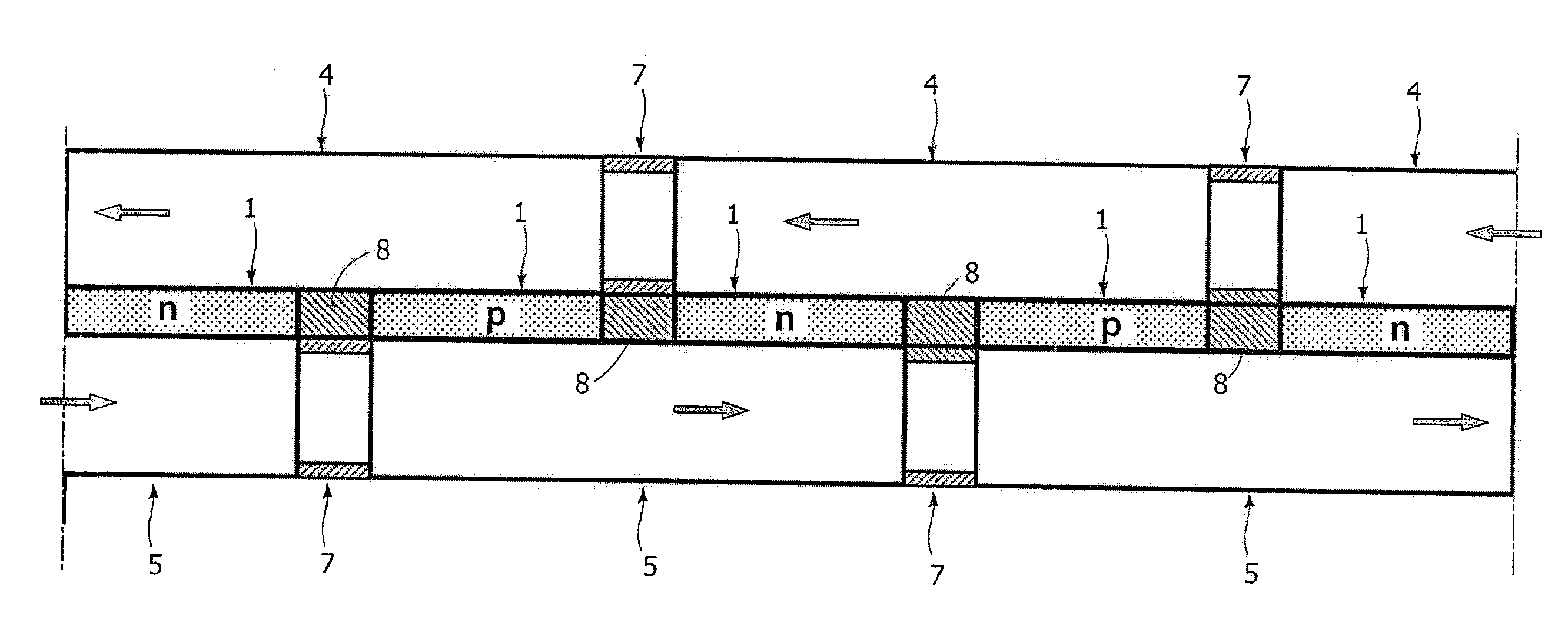
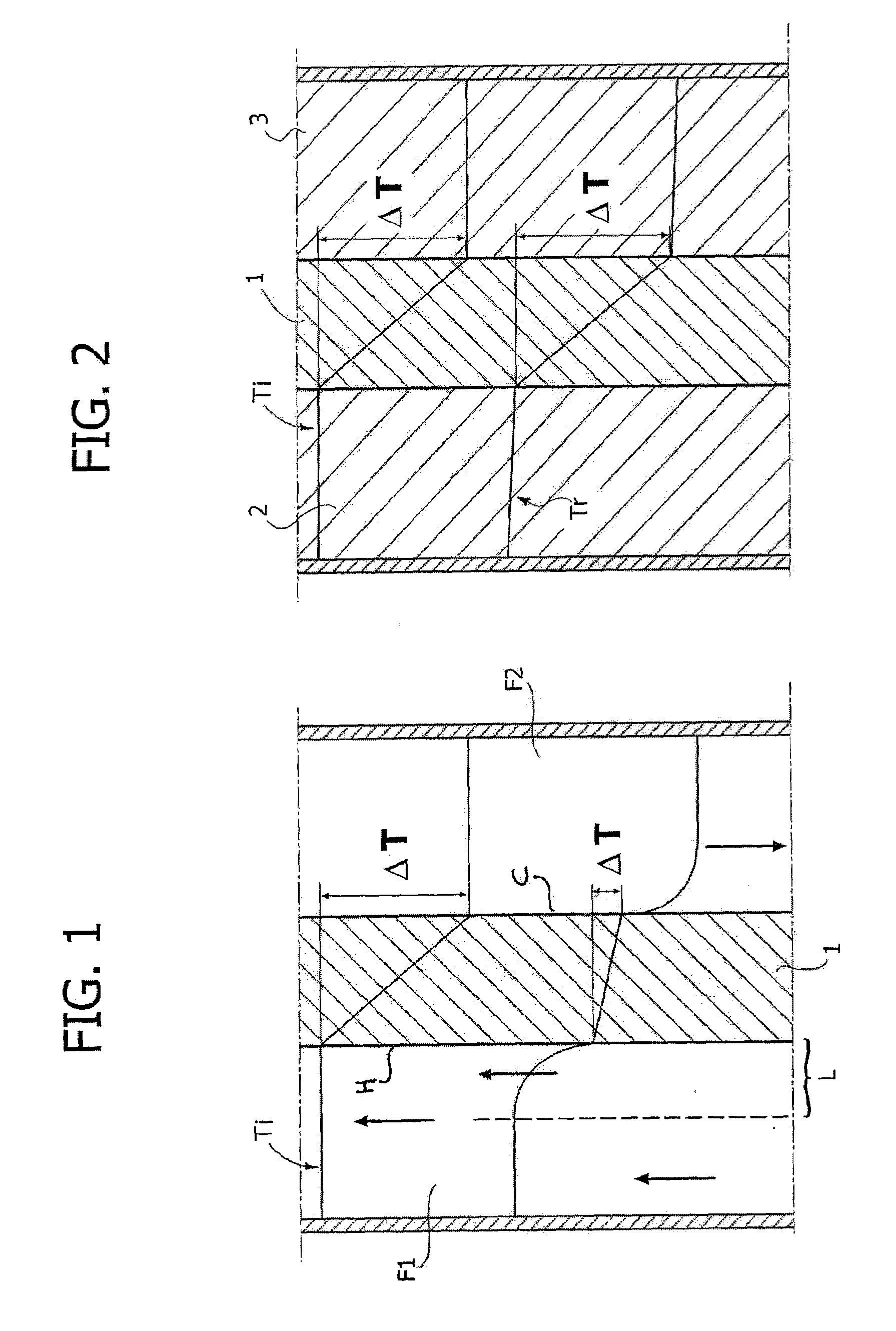
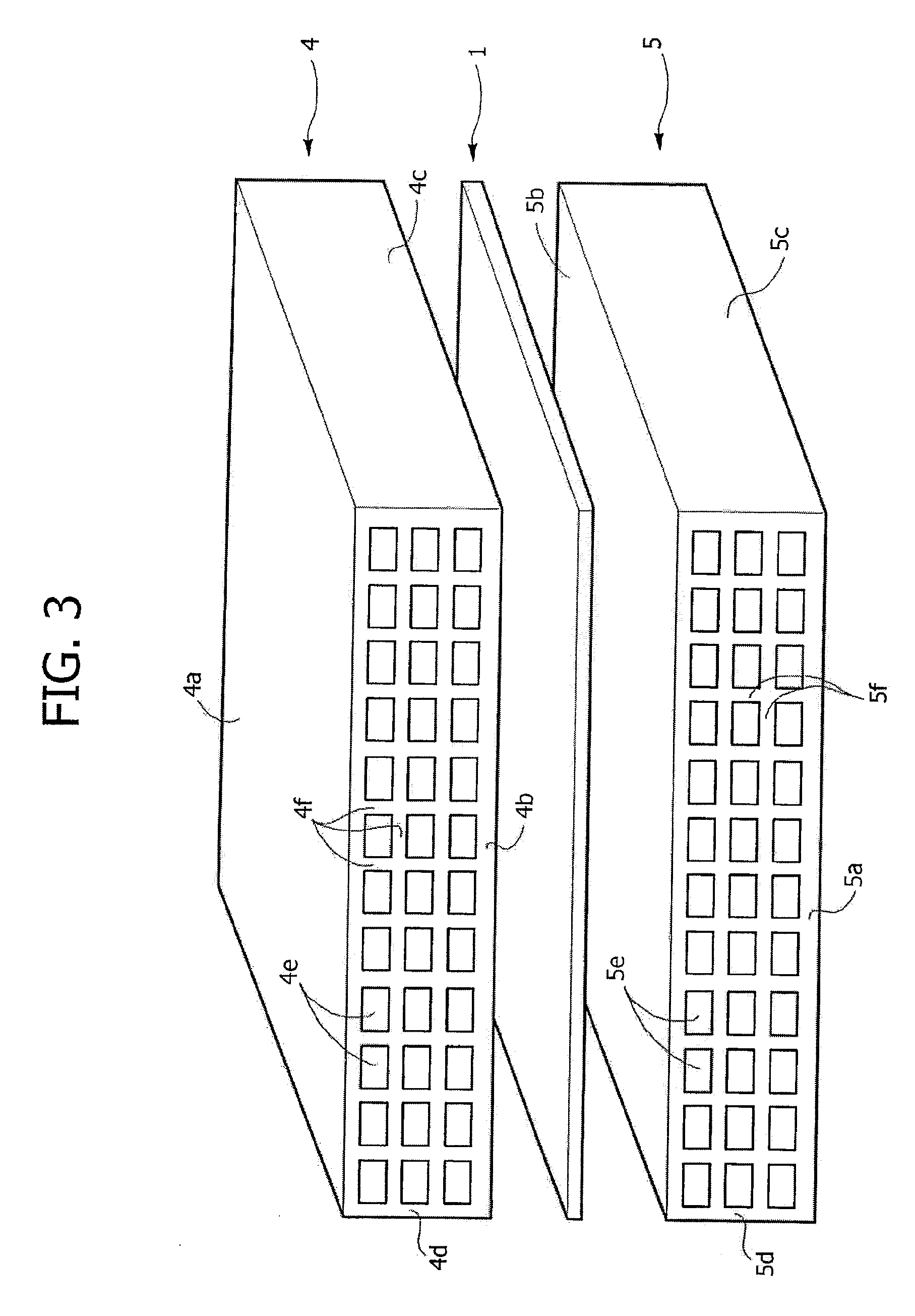
[0033]With reference to FIG. 3, number 1 designates as a whole an element of thermoelectric material in the form of a plate, that can be made in any known way and set between two pipes (or sections of pipe, as will be described in detail in what follows), which are designated, respectively, by 4 and 5 and, in the example illustrated, are each constituted by an extruded element of metal material with high thermal conductivity. As may be seen in the drawing, each pipe 4 has an outer wall defining two main plane and opposite faces 4a, 4b and, respectively, 5a and 5b, and two opposite longitudinal faces 4c, 4d and, respectively, 5c and 5d. The walls define a cavity of passage that is divided into a plurality of sub-channels 4e and 5e by a plurality of diaphragms 4f and 5f orthogonal to one another. The arrangement described above tends to provide a sort of hybrid between the two conventional solutions with gas-solid interface and solid-solid interface, illustrated in FIGS. 1 and 2. In o...


PUM


Abstract

A generator of electric energy based on a thermoelectric effect includes a layer of thermoelectric material set between two pipes that guide two flows of fluid at temperatures different from one another. Each of the pipes has its wall in heat-conduction contact with respective side of the layer of thermoelectric material. Each pipe has a cavity of passage for the respective flow of fluid occupied by a porous material or divided by diaphragms into a plurality of sub-channels so as to obtain a large heat-exchange surface between each flow of fluid and the wall of the respective pipe and between said wall and the respective side of the layer of thermoelectric material.

Description

BACKGROUND OF THE INVENTION[0001]The present invention relates to generators of electric energy based on the thermoelectric effect. In particular, the invention regards a generator of electric energy of the type comprising:[0002]a layer of thermoelectric material; and[0003]means for guiding a first flow of fluid at a higher temperature and a second flow of fluid at a lower temperature in a direction parallel and adjacent to the two opposite sides of the layer of thermoelectric material,[0004]in such a way as to produce a heat transfer through said layer of thermoelectric material, from the side adjacent to the flow of fluid at a higher temperature to the side adjacent to the flow of fluid at a lower temperature[0005]so as to generate a difference of electrical potential between two electrical terminals in electrical connection with the two opposite sides of the layer of thermoelectric material.[0006]In the present description and in the attached claims, the expression “layer of ther...

Claims


Application Information

Patent Timeline
Patent Type & Authority Applications(United States)
IPC IPC(8): H01L35/00H10N10/00H10N10/13H10N10/01H10N10/17
CPCH01L35/32H01L35/30H10N10/13H10N10/17
Inventor BRIGNONE, MAUROZIGGIOTTI, ALESSANDROREPETTO, PIERMARIOLAMBERTINI, VITO GUIDOPERLO, PIERO
Owner CENT RICERCHE FIAT SCPA
Learn More