
Eureka
For R&D, Eureka makes reading and utilizing patents & technical documents easy.
Eureka AIR
Designed for self-driven R&D workflows. Generate viable solutions, solve complex R&D challenges, empower your innovation with AI.

Eureka Materials
Designed for material experts only. Revolutionize your material R&D, from search, analyze, to developing new materials.

TechResearch
Generate reliable direction feasibility study reports for your R&D in just a few steps.

TechSeek
Discover and master advanced knowledge NOW. Basics, ideas, possibilities, all at once.

TechMind
As an expert in R&D Theories, TechMind can generates customized viable solutions instantly.

TechRisk
Analyze your overall solution with one click, know your potential R&D risks in advance.

TechMonitor
Get weekly tech updates, stay abreast of the latest tech innovations and key insights.
Insulated electrical bushing and method of producing the same
- Summary
- Abstract
- Description
- Claims
- Application Information
AI Technical Summary
Benefits of technology
Problems solved by technology
Method used
Image

Examples
first embodiment
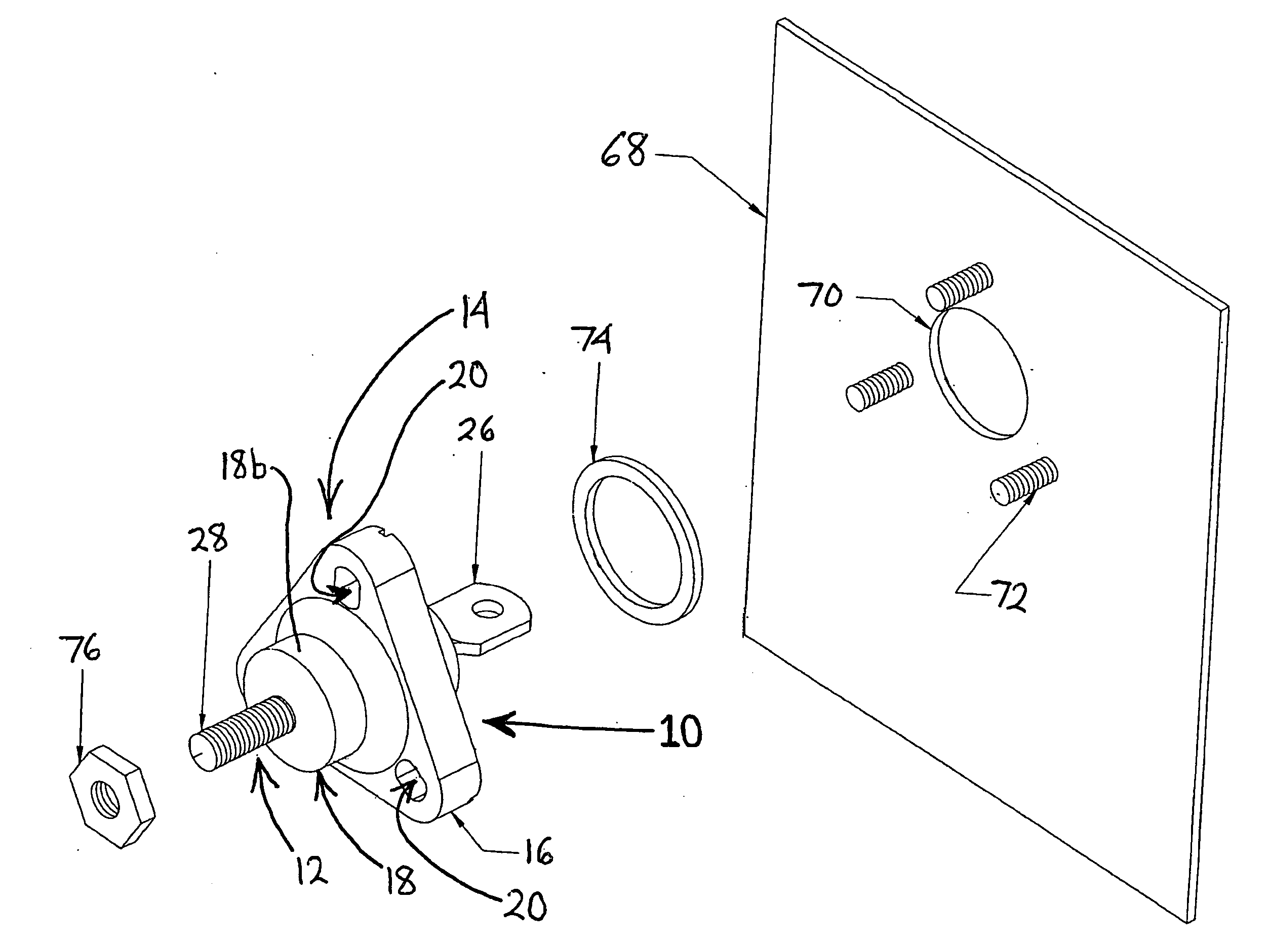
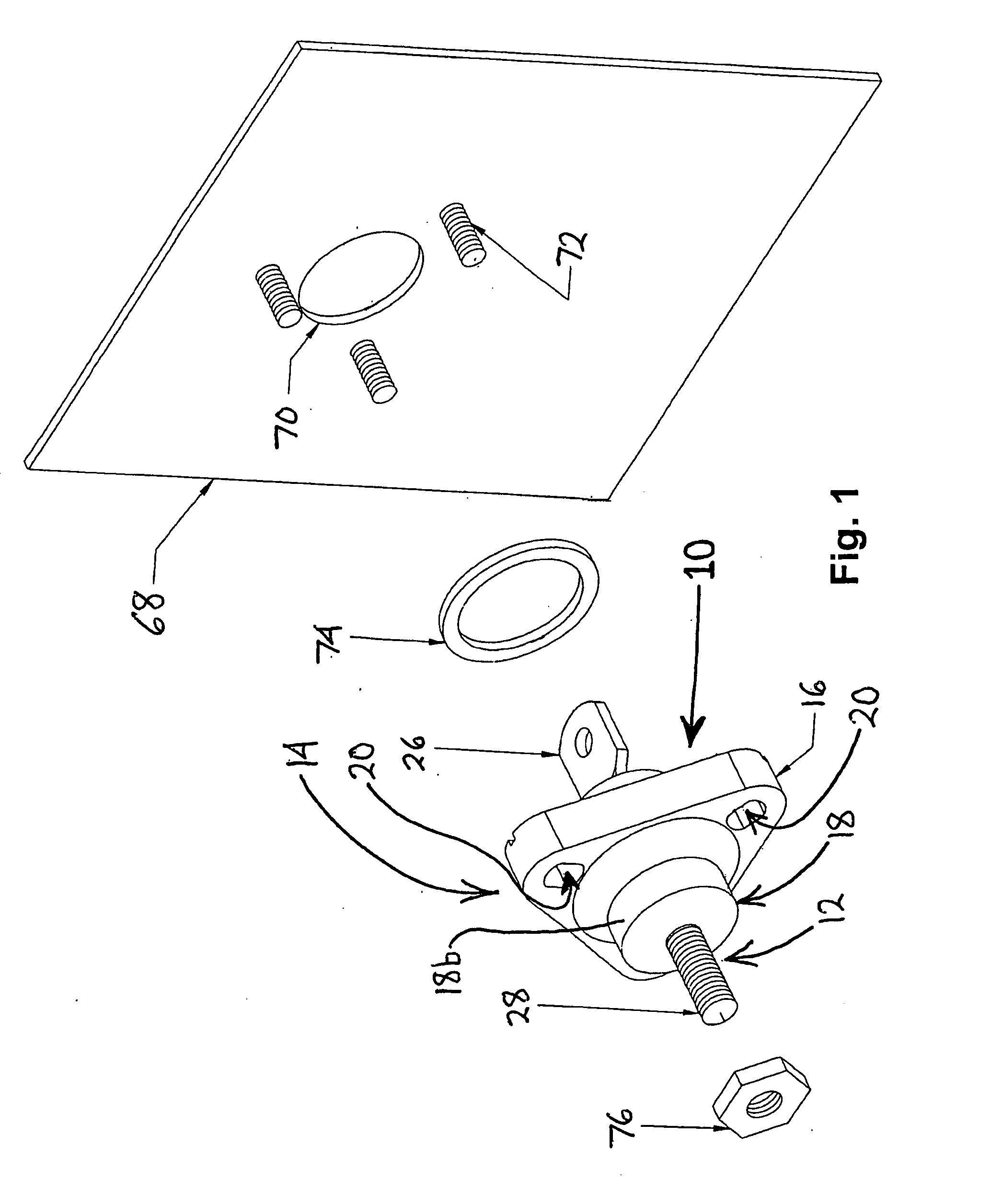
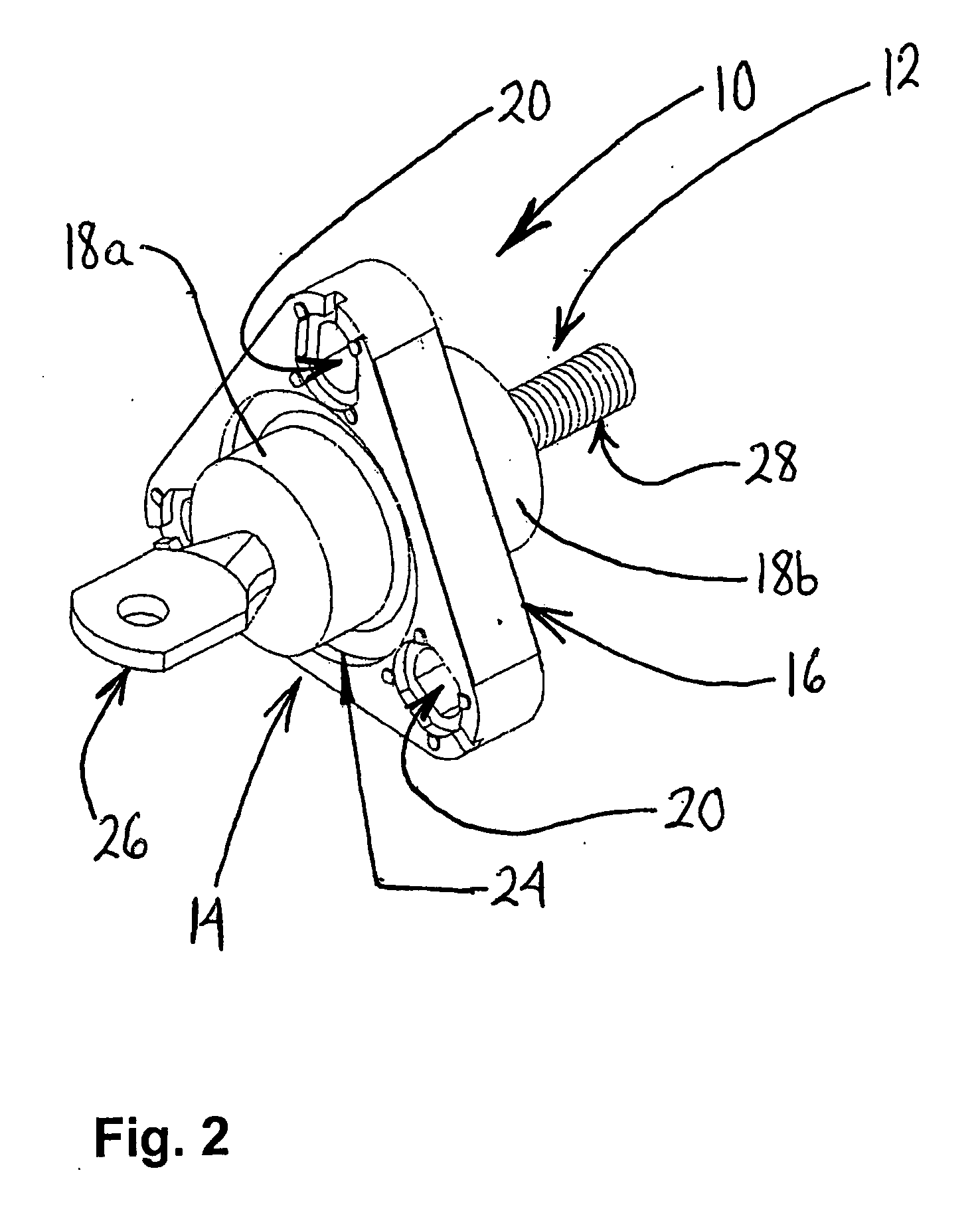
[0024]Referring now to FIGS. 1 and 2, there is shown an electrical bushing 10 constructed in accordance with the present invention. The bushing 10 may be a low voltage bushing adapted for use in a distribution transformer. The bushing 10 includes a conductor 12 and an insulating body 14. As will be described in more detail below, the insulating body 14 is molded around the conductor 12 in an injection over-molding process.
[0025]The insulating body 14 is composed of a dielectric plastic and more particularly a dielectric thermoplastic. Examples of dielectric thermoplastics that may be used to form the insulating body 14 include polyphthalamide or high temperature nylon (HTN), polyethylene terephthalate (PET) and polybutylene terephthalate (PBT). The insulating body 14 includes a triangular flange 16 disposed around a cylindrical main section 18. Mounting openings 20 are located at the three corners of the flange 16, respectively, and extend through the flange 16. At the juncture of t...
second embodiment
[0036]Referring now to FIGS. 7 and 8, there is shown a conductor 80 of an electrical bushing constructed in accordance with the present invention. An insulating body (not shown) is molded over the conductor 80.
[0037]The conductor 80 is composed of a conductive metal, such as copper. The conductor 80 is elongated and includes a middle section 82 disposed between a first threaded portion 84 and a second threaded portion 86. The first and second threaded portions 84, 86 each have a continuous helical thread. The middle section 82 includes a first embossment region 88, a second embossment region 90, a third embossment region 92 and a fourth embossment region 94. The first and second threaded portions 84, 86, and the first, second, third and fourth embossment regions 88, 90, 92 and 94 are all produced by roll forming.
[0038]The first embossment region 88 comprises a pattern of protuberances disposed around the circumference of the conductor 80. The protuberances may be straight knurls, di...
third embodiment
[0041]Referring now to FIGS. 9, 10 and 11, there is shown a conductor 110 of an electrical bushing constructed in accordance with the present invention. An insulating body (not shown) is molded over the conductor 110.
[0042]The conductor 110 is composed of a conductive metal, such as copper, and is elongated. The conductor 110 includes a threaded end portion 112 and a body portion 114 having a plurality of embossment regions. The threaded end portion 112 has a continuous helical thread. The body portion 114 has a first embossment region 116, a second embossment region 118 and a third embossment region 120. The threaded end portion 112, and the first, second, and third embossment regions 116, 118 and 120 are all produced by roll forming. An axially-extending bore 122 is formed in the body portion 114. An annular flange 121 is disposed around the bore 122 and is joined to the body portion 114.
[0043]The first and third embossment regions 116, 120 each comprise a plurality of annular rin...
PUM
| Property | Measurement | Unit |
|---|---|---|
| Temperature | aaaaa | aaaaa |
| aaaaa | aaaaa |
Abstract
Description
Claims
Application Information
 - R&D Engineer
- R&D Manager
- IP Professional
- Industry Leading Data Capabilities
- Powerful AI technology
- Patent DNA Extraction
Browse by: Latest US Patents, China's latest patents, Technical Efficacy Thesaurus, Application Domain, Technology Topic, Popular Technical Reports.
© 2024 PatSnap. All rights reserved.Legal|Privacy policy|Modern Slavery Act Transparency Statement|Sitemap|About US| Contact US: help@patsnap.com