Calibration of radiographic images

a radiographic image and image technology, applied in the field of images, can solve the problems of insufficient accuracy of solutions and body three-dimensionality

Active Publication Date: 2008-03-13
BRAINLAB
View PDF9 Cites 75 Cited by
  • Summary
  • Abstract
  • Description
  • Claims
  • Application Information

AI Technical Summary

Problems solved by technology

A major difficulty encountered when interpreting radiographic images is that the body is three dimensional.
However, such solutions are not accurate enough, too cumbersome, or are inconvenient.

Method used


Image

  • Calibration of radiographic images
  • Calibration of radiographic images
  • Calibration of radiographic images

Examples


Embodiment Construction

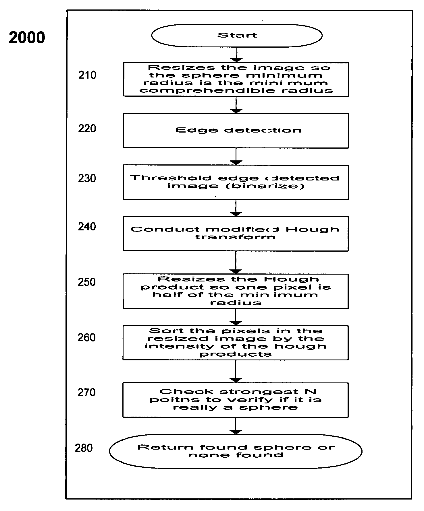
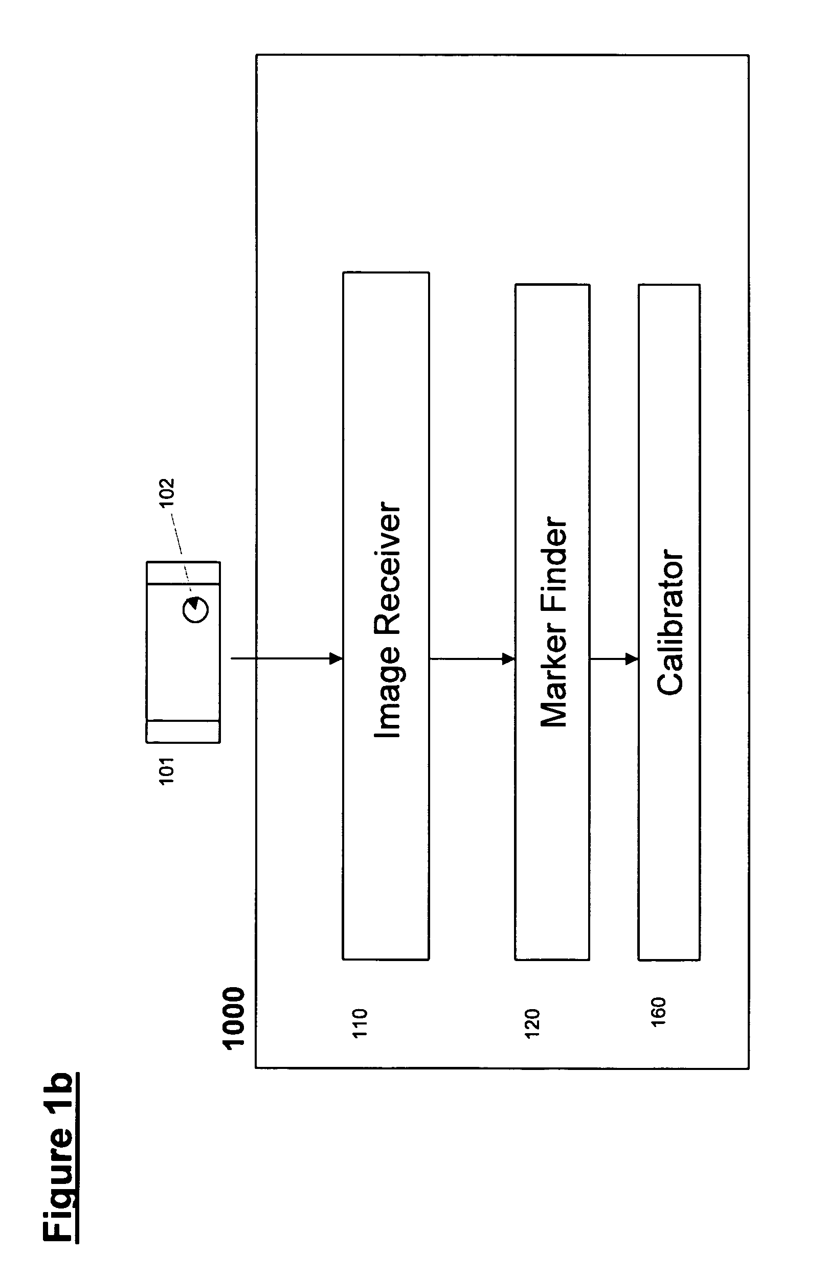
[0043]The present embodiments comprise an apparatus and a method for calibrating an image through finding a spherical calibration marker in the image.

[0044]Present embodiments of the present invention may be used for calibrating radiographic images.

[0045]While the body organs are three dimensional, a regular radiographic image is planar or two-dimensional. Even if the patient is at a fixed distance from a radiographic camera, the image plane may depend on the position of the bone or organ of interest.

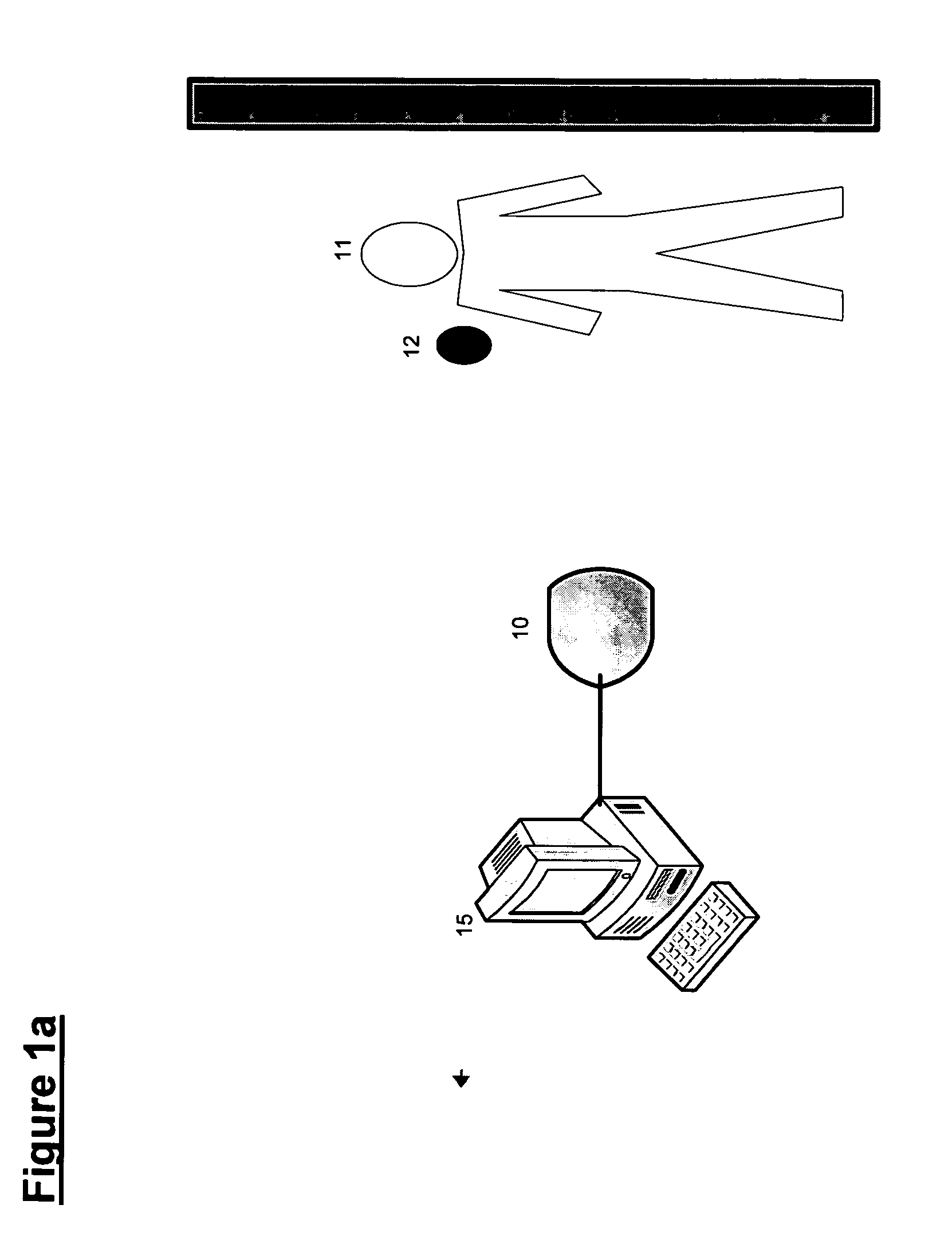
[0046]Reference is now made to FIG. 1a, which is a block diagram illustrating a radiographic imaging scenario, according to a preferred embodiment of the present invention.

[0047]As shown in FIG. 1a, a patient 11 may be imaged using an X-ray camera 10 together with a spherical calibration marker 12 positioned next to the patient 11. A spherical calibration marker 12 has the advantage of having the same circular image, regardless of the position of the camera 10 relative to the marker 12....


PUM


Abstract

Apparatus for calibrating an image, the image comprising a spherical marker, the apparatus comprising: an image receiver, configured to receive the image, and a marker finder, associated with the image receiver and configured to automatically find an image of the marker in the received image.

Description

FIELD AND BACKGROUND OF THE INVENTION[0001]The present invention relates to calibration of images and more particularly, but not exclusively to an apparatus and method for calibration of radiographic images.[0002]In the interpretation of images such as radiographic images, various approaches are known for differentiating between structures which appear in such images.[0003]A major difficulty encountered when interpreting radiographic images is that the body is three dimensional. However, even if the patient is positioned is a known distance from the radiographic camera, the image plane may vary according to an organ or bone of interest. That is to say, the camera may zoom-in or zoom-out, so as to focus at the organ or bone of interest. Consequently, there arises a need to know the scale of the resultant radiographic image, in order to identify the organ (or bone) of interest, accurately estimate the bone dimensions, etc.[0004]U.S. Pat. No. 4,506,676, to Duska, entitled “Radiographic...

Claims


Application Information

Patent Timeline
Patent Type & Authority Applications(United States)
IPC IPC(8): G06K9/00G06K9/32
CPCA61B6/583A61B6/12
Inventor RUSSAK, ZEEVGLOZMAN, ZEEV
Owner BRAINLAB
Why Eureka
Try Eureka