Digital single-reflex camera

a digital camera and single-reflex technology, applied in the direction of printers, exposure control, camera focusing arrangement, etc., can solve the problems of prior art having the problem of not being able to perform control efficiently, and information obtained before mode switching has not necessarily been used effectively after, so as to achieve the effect of performing control efficiently

Inactive Publication Date: 2006-06-15
KONICA MINOLTA PHOTO IMAGING
View PDF2 Cites 61 Cited by
  • Summary
  • Abstract
  • Description
  • Claims
  • Application Information

AI Technical Summary

Benefits of technology

[0010] It is therefore an object of the invention is to provide a

Problems solved by technology

In prior art digital cameras, when the display mode is switched from one to the other, information obtained before the mode switching has not neces

Method used


Image

  • Digital single-reflex camera
  • Digital single-reflex camera
  • Digital single-reflex camera

Examples


Embodiment Construction

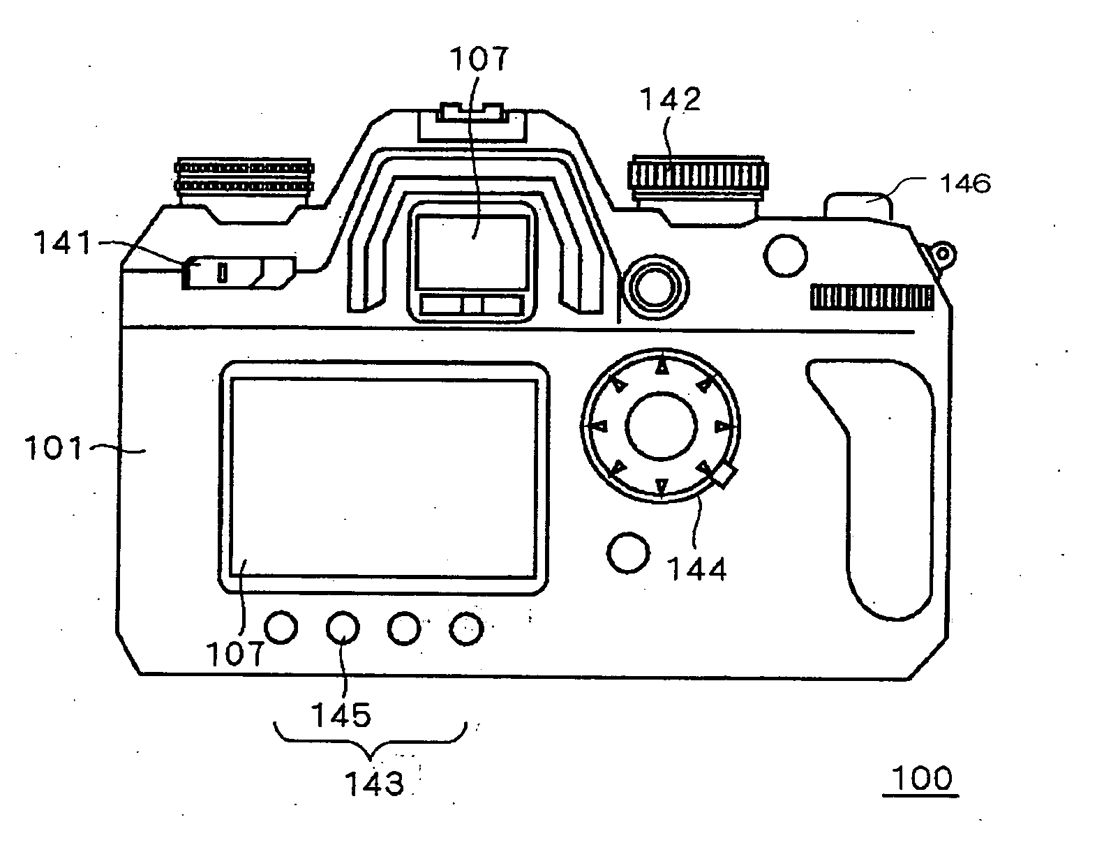
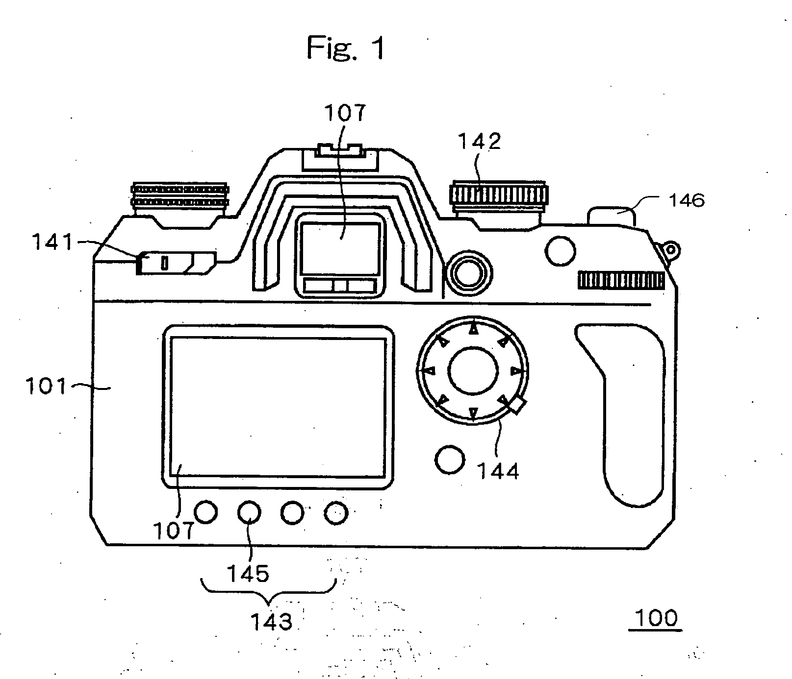
[0032] In a digital single-reflex camera according to an embodiment of the present invention, when effecting switching between the optical viewfinder mode and the live view mode, focusing information relating to AF (auto focusing) and exposure control information relating to AE (auto exposure control) obtained before the mode switching are stored for use after the mode switching. The focusing information includes the measured focus detection result (range value) taken before the mode switching and information concerning the subject's two-dimensional position on the display screen at the time of the focus detection. The exposure control information includes the metered light value taken before the mode switching and information concerning the subject's two-dimensional position on the display screen at the time of the light metering.

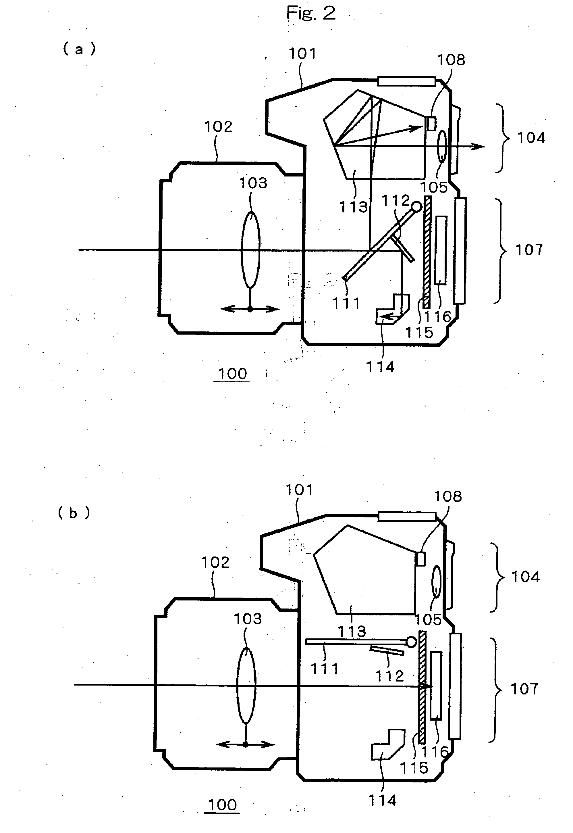
[0033]FIG. 1 is a rear view of a digital single-reflex camera 100 according to a first embodiment of the present invention. FIG. 2 is a cross sectional s...


PUM


Abstract

When a selector button is pressed in optical viewfinder mode, a display in live view mode is started. If the metered light value, measured focus detection result, and position information stored in the optical viewfinder mode are set so as to be reflected in the live view mode, exposure control is performed based on the stored metered light value and position information, and focusing is performed based on the stored focus detection result and position information.

Description

[0001] This application is based on the application No. 2004-356253 filed in Japan, the contents of which are hereby incorporated by reference. BACKGROUND OF THE INVENTION [0002] 1. Field of the Invention [0003] The present invention relates to a digital single-reflex camera. [0004] 2. Description of the Related Art [0005] Generally, digital cameras have two display modes: the mode that displays the subject through an optical viewfinder (hereinafter called the optical viewfinder mode), and the mode that displays the captured image on a monitor at the rear of the camera (hereinafter called the live view mode). In such digital cameras, one or the other of the display modes can be selected using a selector button. [0006] Usually, the digital camera shoots an image after performing AF (auto focusing) and AE (auto exposure control) in the selected display mode. AF based on phase difference (hereinafter called the phase difference AF) and AF based on contrast detection (hereinafter called...

Claims


Application Information

Patent Timeline
IPC IPC(8): G03B13/34
CPCG03B7/08G03B13/36G03B17/18G03B19/12H04N5/23212H04N5/23245H04N5/2351H04N2101/00H04N23/672H04N23/673H04N23/667H04N23/635H04N23/71
Inventor MORI, NOBUYUKIYOKOTA, SATOSHIICHIKAWA, TSUTOMUAKESAKA, MAKOTOKAGEYAMA, KAZUMI
Owner KONICA MINOLTA PHOTO IMAGING
Why Eureka
Try Eureka