Driving device, projector, and driving method

a driving device and projector technology, applied in the direction of printers, instruments, camera focusing arrangement, etc., can solve the problems of difficult to provide the location sensor, and difficult to move the lens to a proper location, etc., to achieve efficient control

Active Publication Date: 2014-03-27
SEIKO EPSON CORP
View PDF3 Cites 3 Cited by
  • Summary
  • Abstract
  • Description
  • Claims
  • Application Information

AI Technical Summary

Benefits of technology

[0035]As described above, according to the aspects of the invention, the driving device, the projector, and the driving method can efficiently perform control related to the backlash, respectively, and can be applied to others than the backlash.

Problems solved by technology

A driving system of a lens structurally has backlash, and when driving the lens in a reverse direction with respect to a last moving direction, it is difficult to move the lens to a proper location due to influence of the backlash.
However, when aiming to achieve miniaturization of the device, the location sensor is not always provided near the motor as the configuration described above.
In this case, since a driving target starts moving before the location sensor detects the location, it is difficult for the location sensor to detect the movement of driving target, and a movement amount acquired from the location sensor becomes smaller than the actual movement amount.
Accordingly, for example, a method of moving extra backlash part (for example, see Japanese Patent No. 3208802) is difficult to be used since the movement detected by the location sensor is smaller than the movement of the driving target.
In addition, a method of filling the backlash part (for example, see JP-A-10-160999) is difficult to be used since the driving target is moved before the backlash related to the location sensor is filled.
A method of measuring the backlash amount at low torque driving (for example, see JP-A-2007-187712) is difficult to be used since the change of the moving rate does not occur due to the movement of the driving target before the movement of the location sensor.
As described above, on the other hand, with respect to the configuration of the related art of providing the location sensor nearer to the motor than the driving target, in a configuration of providing the driving target nearer to the motor than the location sensor, a location relationship between the driving target and the location sensor is reversed, and the methods related to the backlash which were effective in the configuration of the related art (for example, see Japanese Patent No. 3208802, JP-A-10-160999, and JP-A-2007-187712) are difficult to be used.

Method used


Image

  • Driving device, projector, and driving method
  • Driving device, projector, and driving method
  • Driving device, projector, and driving method

Examples


Embodiment Construction

[0047]Embodiments of the invention will be described in detail with reference to the drawings.

Outline of Projector According to the Embodiment

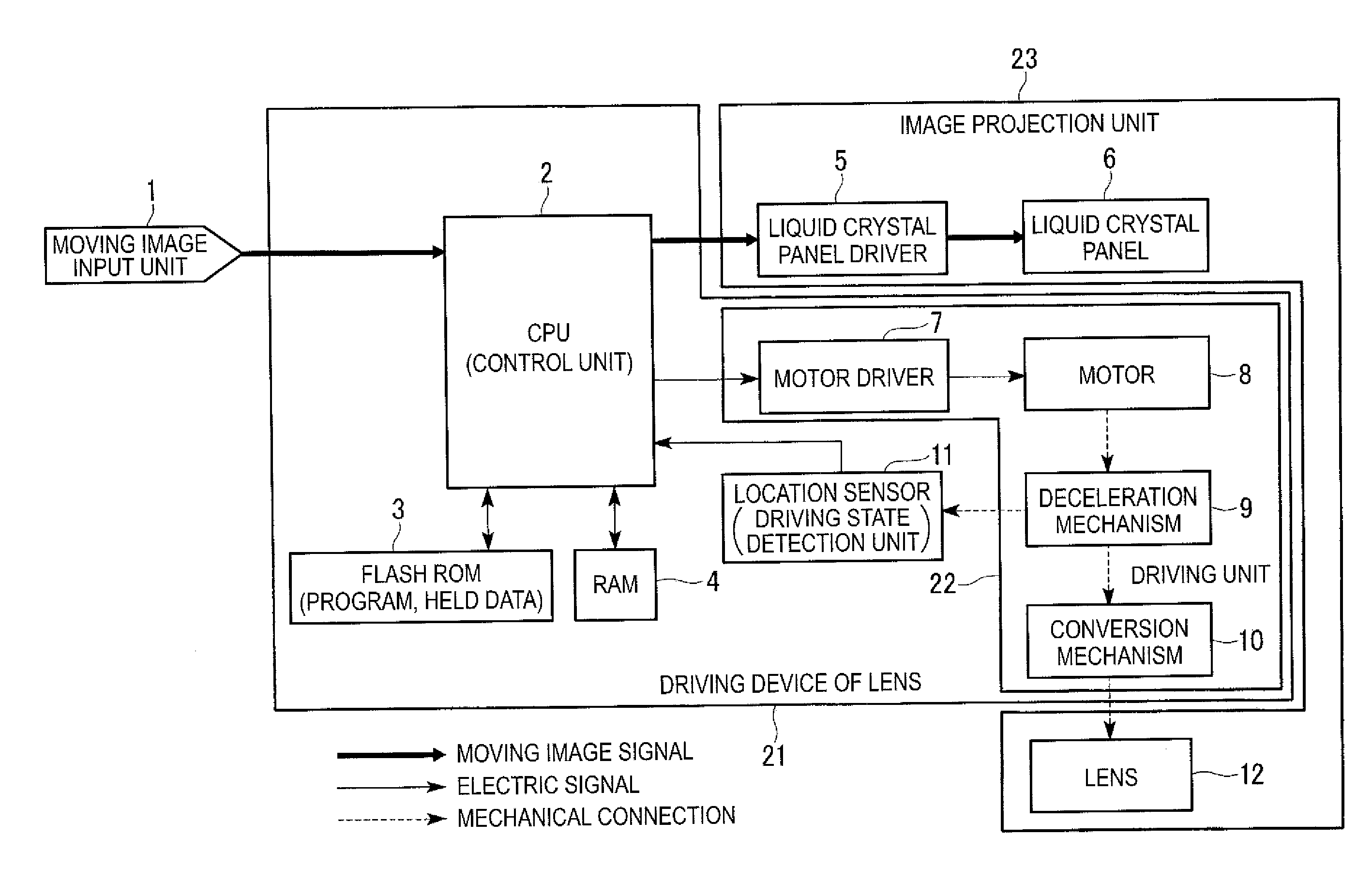
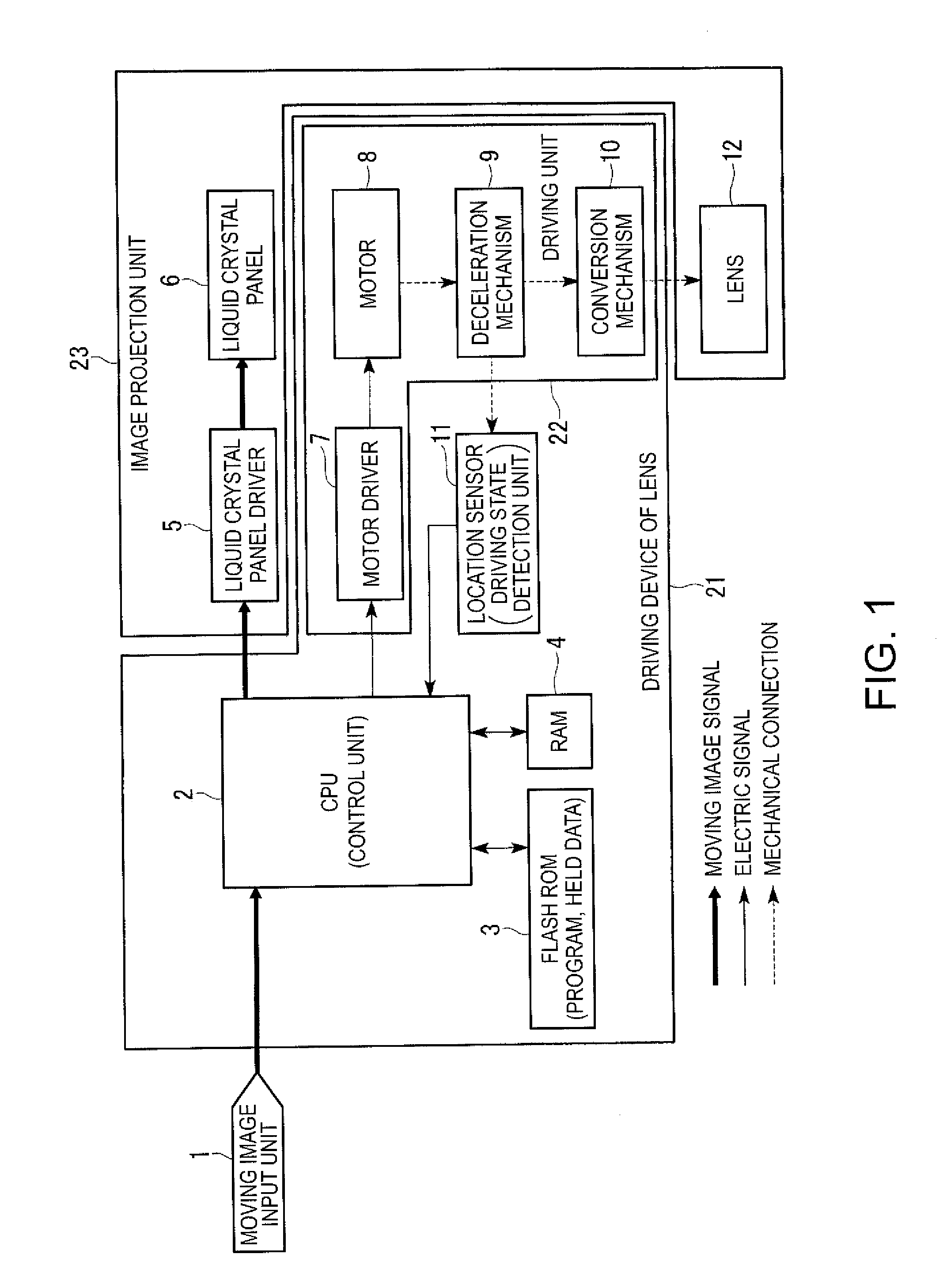
[0048]FIG. 1 is a block diagram showing a schematic configuration example of a projector according to an embodiment of the invention.

[0049]The projector according to the embodiment includes a moving image input unit 1, a Central Processing Unit (CPU) 2, a flash Read Only Memory (ROM) 3, a Random Access Memory (RAM) 4, a liquid crystal panel driver 5, a liquid crystal panel 6, a motor driver 7, a motor 8, a deceleration mechanism 9, a conversion mechanism 10, a location sensor 11, and a lens 12.

[0050]Herein, in the embodiment, an electric driving device 21 of the lens 12 includes the CPU 2, a memory (in the embodiment, the flash ROM 3 and the RAM 4), the motor driver 7, the motor 8, the deceleration mechanism 9, the conversion mechanism 10, and the location sensor 11.

[0051]In the embodiment, a driving unit (driving system) 22 of the driving dev...


PUM


Abstract

A driving device includes: a driving state detection unit which detects a driving state of a driving unit which drives a driving target; and a control unit which performs a first control for driving the driving unit for an amount based on the driving state of the driving unit detected by the driving state detection unit and a second control for driving the driving unit for a predetermined amount.

Description

[0001]The entire disclosure of Japanese Patent Application No. 2012-211899, filed Sep. 26, 2012 is expressly incorporated by reference herein.BACKGROUND[0002]1. Technical Field[0003]The present invention relates to a driving device, a projector, and a driving method.[0004]2. Related Art[0005]In a projector or the like, a location of a lens is controlled by a driving device.[0006]A driving system of a lens structurally has backlash, and when driving the lens in a reverse direction with respect to a last moving direction, it is difficult to move the lens to a proper location due to influence of the backlash.[0007]In an example of a general configuration, a location sensor is provided near a motor, the location is detected by the location sensor in advance, a driving target (herein, lens) exists on a rear stage thereof, and accordingly, if the motor starts moving, the location sensor reacts in advance, and then, the driving target starts moving. Thus, the backlash can be compensated ba...

Claims


Application Information

Patent Timeline
Patent Type & Authority Applications(United States)
IPC IPC(8): G02B7/09
CPCG02B7/09G02B7/08G03B3/10G03B21/142G03B21/53
Inventor TSUKAGOSHI, SHINICHI
Owner SEIKO EPSON CORP
Why Eureka
Try Eureka