Photographic device and control method therefor

a technology of a photographic device and a control method, which is applied in the field of photographic devices, can solve the problems of reducing the effect of the inability to keep the electronic shutter speed at a value, and the inability to implement a general timing generator, so as to achieve the effect of reducing the release time lag

Inactive Publication Date: 2005-09-15
FUJIFILM CORP
View PDF7 Cites 61 Cited by
  • Summary
  • Abstract
  • Description
  • Claims
  • Application Information

AI Technical Summary

Benefits of technology

[0012] In view of the foregoing, a primary object of the present invention is to provide a photographic device and a control method therefore, which reduce the release time lag effectively without the need for a specific timing generator.
[0013] To achieve the above and other objects, the present invention provides a photographic device that comprises a release button movable to a half-pressed position and a full-pressed position; an image sensor having a function of an electronic shutter and converting an optical image of a subject to a still image signal, the image sensor shooting video images while the release button is not pressed or is kept in the half-pressed position, and photographing a still image when the release button is moved to the full-pressed position; a display device for displaying images on the basis of still image signals output from the image sensor; an exposure control device that sets an electronic shutter speed of the image sensor, an aperture value and a photosensitivity according to subject brightness based on a first program while the release button is not pressed, the first program setting the electronic shutter speed to be a value preventive against flicker in a low brightness range, the exposure control device deciding an aperture value for still image photography upon the release button being pressed halfway, and so long as the release button is kept in the half-pressed position, the exposure control device using an aperture-priority type second program for setting an electronic shutter speed and a photosensitivity according to subject brightness while applying the aperture value for still image photography to the second program; and a frame rate setting device that sets a first frame rate as a frame rate of the image sensor while the release button is not pressed, and sets a second frame rate as the photographic frame so long as the release button is kept in the half-pressed position, the second frame rate being adapted to prevent flicker.
[0019] using while the release button is kept in the half-pressed position, an aperture-priority type second program for setting an electronic shutter speed and a photosensitivity according to subject brightness while applying the aperture value for still image photography to the second program and using a frame rate adapted to prevent flicker.
[0030] Since the frame rate preventive against the flicker is used for shooting video images while the release button is pressed halfway, the flicker will not occur even if the shutter speed is changed during this condition. Since the aperture value is determined for still image photography up on the release button being pressed halfway, and is fixed at this value so long as the release button is kept being pressed, it is unnecessary to change the aperture value in response to the release button being pressed to the full. Therefore the release time lag is reduced.

Problems solved by technology

So it becomes impossible to keep the electronic shutter speed at a value preventive against the flicker.
In addition to that, although the method disclosed in the above prior art is effective for reducing the release time lag, this prior method needs a specific timing generator, and cannot be embodied with a general timing generator.
Since the conventional digital camera validates content set in the timing generator in synchronism with the vertical synchronizing signal, there is a delay from the shutter release to the actual start of an exposure for photographing a still image.
But because there is a limit in the available range of frequency of the vertical synchronizing signal, this method cannot sufficiently reduce the delay and the release time lag.

Method used


Image

  • Photographic device and control method therefor
  • Photographic device and control method therefor
  • Photographic device and control method therefor

Examples


Embodiment Construction

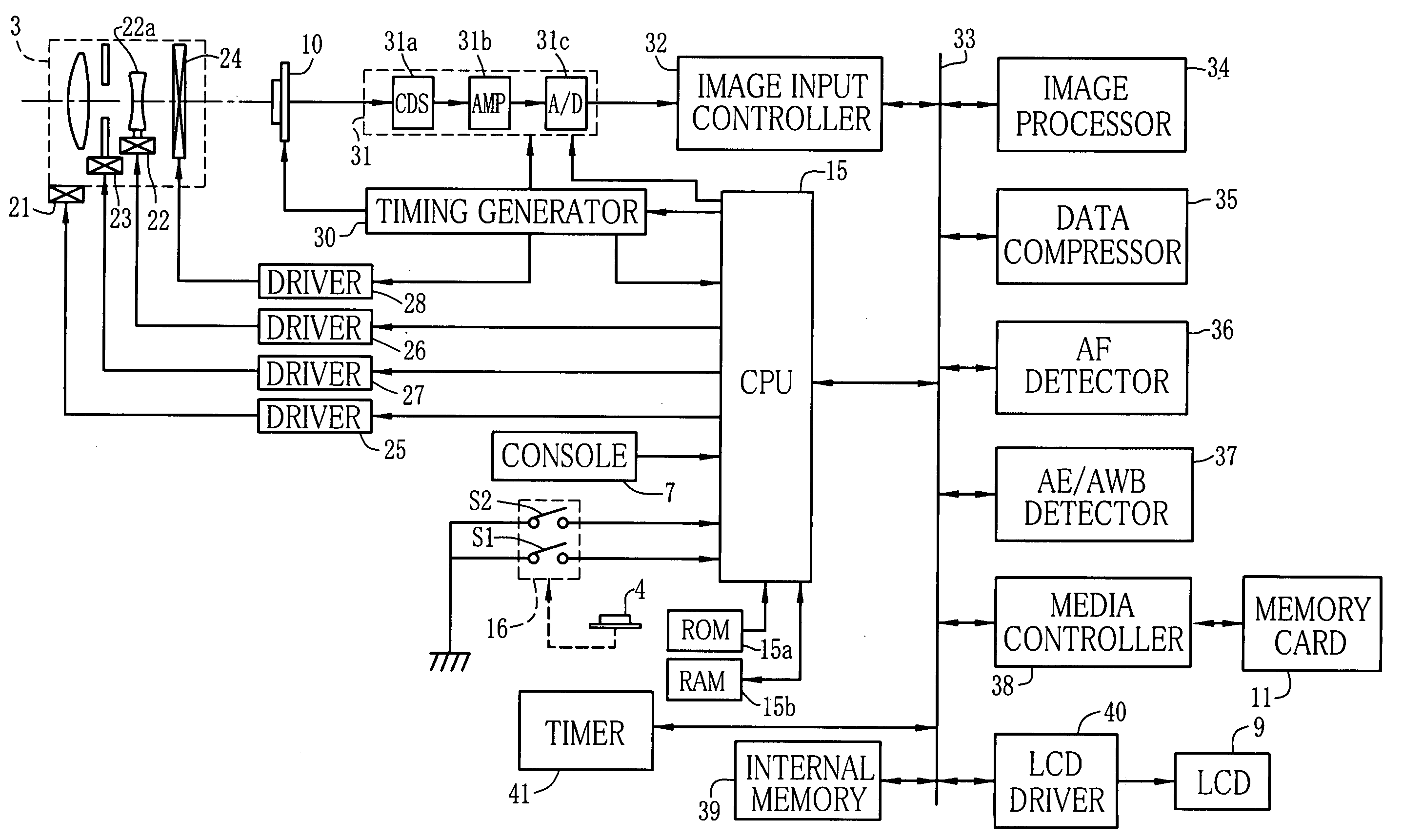
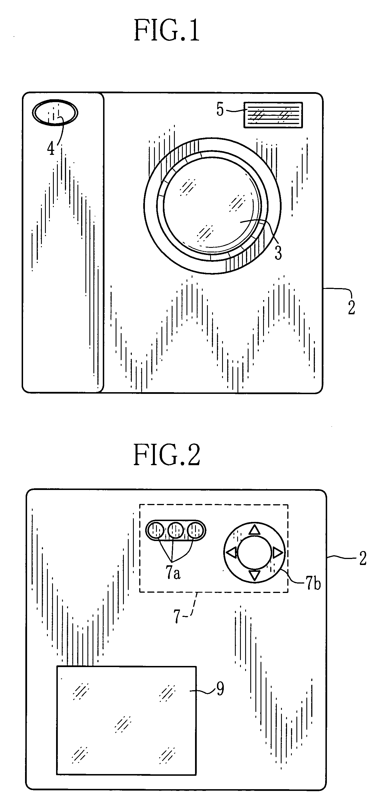
[0051] As shown in FIGS. 1 and 2, a digital camera has a photographic lens 3 with zooming function, a release button 4 and a flash window 5 on a front side of its camera body 2, and a console 7 consisting of control buttons 7a and a cursor key 7a, and an LCD 9 on a rear side of the camera body 2.

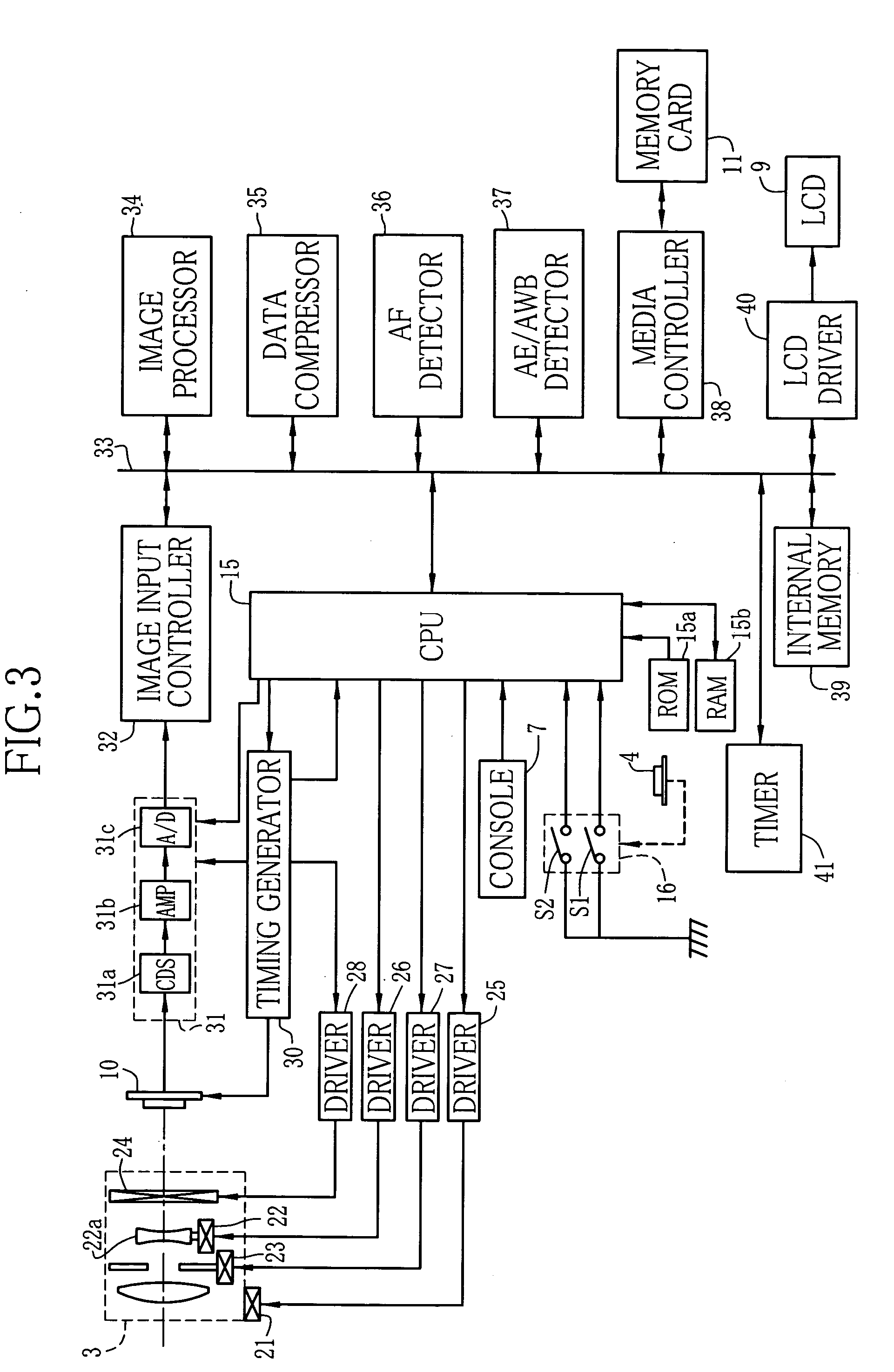
[0052] The release button 4 can be pressed down in two steps: halfway and full. So long as the release button 4 is not pressed in a camera mode, still image signals of subjects are continually picked up through a CCD image sensor 10 that is located behind the photographic lens 3, as shown in FIG. 3, and the LCD 9 displays a slew of video images based on the still image signals currently picked up through the CCD image sensor 10. So the LCD 9 functions as an electronic viewfinder.

[0053] Upon the release button 4 being pressed halfway, a first preparation process is carried out. The first preparation process consists of an AE (automatic exposure) process for deciding a shutter speed, an aper...


PUM


Abstract

There is disclosed a photographic device that uses an image sensor and an electronic viewfinder. When a release button is pressed halfway, an aperture value, an electronic shutter speed and a photosensitivity are decided based on the present subject brightness to provide a proper exposure value for photographing a still image. So long as the release button is kept being pressed halfway, a timing generator drives the image sensor to shoot video images at a frame rate of 20 Hz, and the aperture value decided for still image photography is fixed, whereas the electronic shutter speed and the photosensitivity are adjusted according to the subject brightness by use of an aperture-priority type video program. When the release button is pressed to the full, an exposure for a still image is done with the fixed aperture value.

Description

FIELD OF THE INVENTION [0001] The present invention relates to a photographic device like a digital camera and a control method for this photographic device. BACKGROUND ARTS [0002] Digital cameras have been widely used, wherein subjects are photographed through an imaging device such as a CCD image sensor. The digital camera shoots video images, and displays a slew of video images on a liquid crystal display that serves as an electronic viewfinder. In response to a release button being pressed, the digital camera photographs a still image and records data of the photographed still image on a recording medium like a memory card. There are such digital cameras that can record video image data. [0003] In such a digital camera, the image sensor is exposed and read out generally at a frame rate or shooting frequency of 30 Hz, i.e. 30 frames per second, in synchronism with the recording and displaying of the video images. Meanwhile, there are two kinds of frequencies of commercial power s...

Claims


Application Information

Patent Timeline
Patent Type & Authority Applications(United States)
IPC IPC(8): H04N5/235H04N5/232
CPCH04N5/23245H04N2101/00H04N5/2353H04N5/2352H04N23/667H04N23/72H04N23/73
Inventor KOBAYASHI
Owner FUJIFILM CORP
Why Eureka
Try Eureka