Imaging apparatus and imaging method for reducing release time lag

a technology of imaging apparatus and release time lag, which is applied in the field of imaging apparatus, an imaging method, a program, and a recording medium, can solve the problems of increasing power consumption, increasing circuit area, and increasing cost, so as to reduce the release operation and reduce the release time lag , the effect of increasing power consumption

Inactive Publication Date: 2009-09-15
RICOH KK
View PDF12 Cites 3 Cited by
  • Summary
  • Abstract
  • Description
  • Claims
  • Application Information

AI Technical Summary

Benefits of technology

[0013]Therefore, for example, the starting time of the exposure setup from the shutter release button is pressed for the release operation can be shortened comparing to the conventional method. Moreover, since the processing can be conducted by the software processing, reading out each electric charge i

Problems solved by technology

More specifically, when reading out the electric charge in a monitoring operation and a recording operation for monitoring an object before photographing, because what are disclosed in the prior art references as descr

Method used


Image

  • Imaging apparatus and imaging method for reducing release time lag
  • Imaging apparatus and imaging method for reducing release time lag
  • Imaging apparatus and imaging method for reducing release time lag

Examples


first embodiment

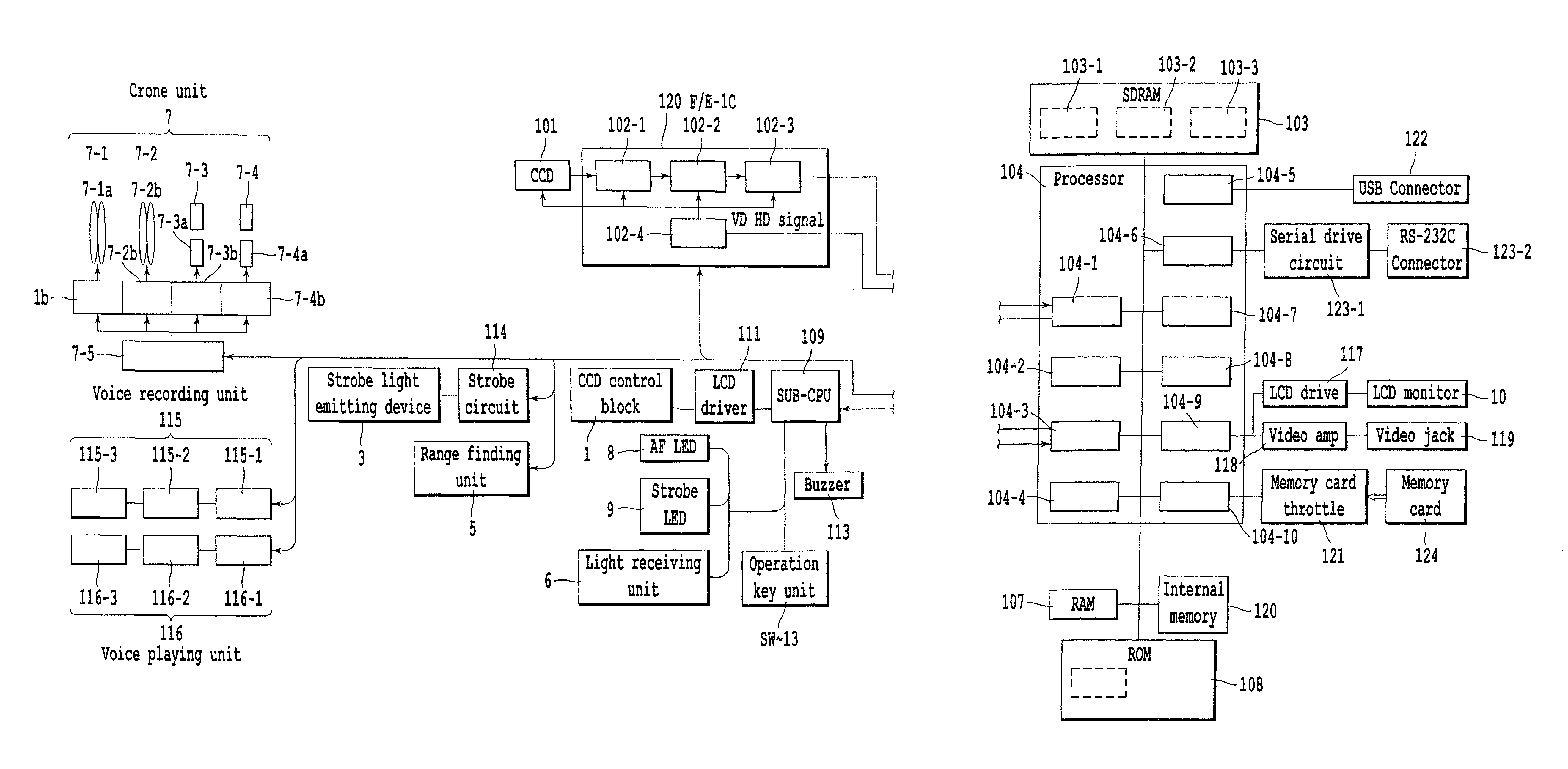
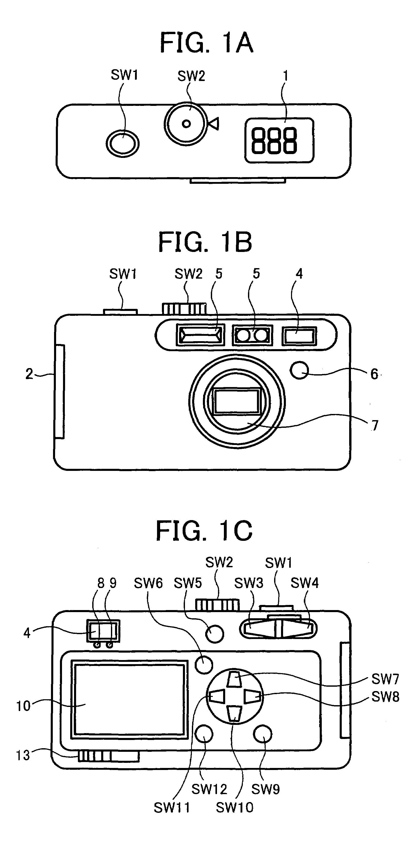
[0026]FIG. 1A, 1B, and 1C illustrate the appearance of digital camera which is an example of imaging apparatus according to the present invention, respectively.

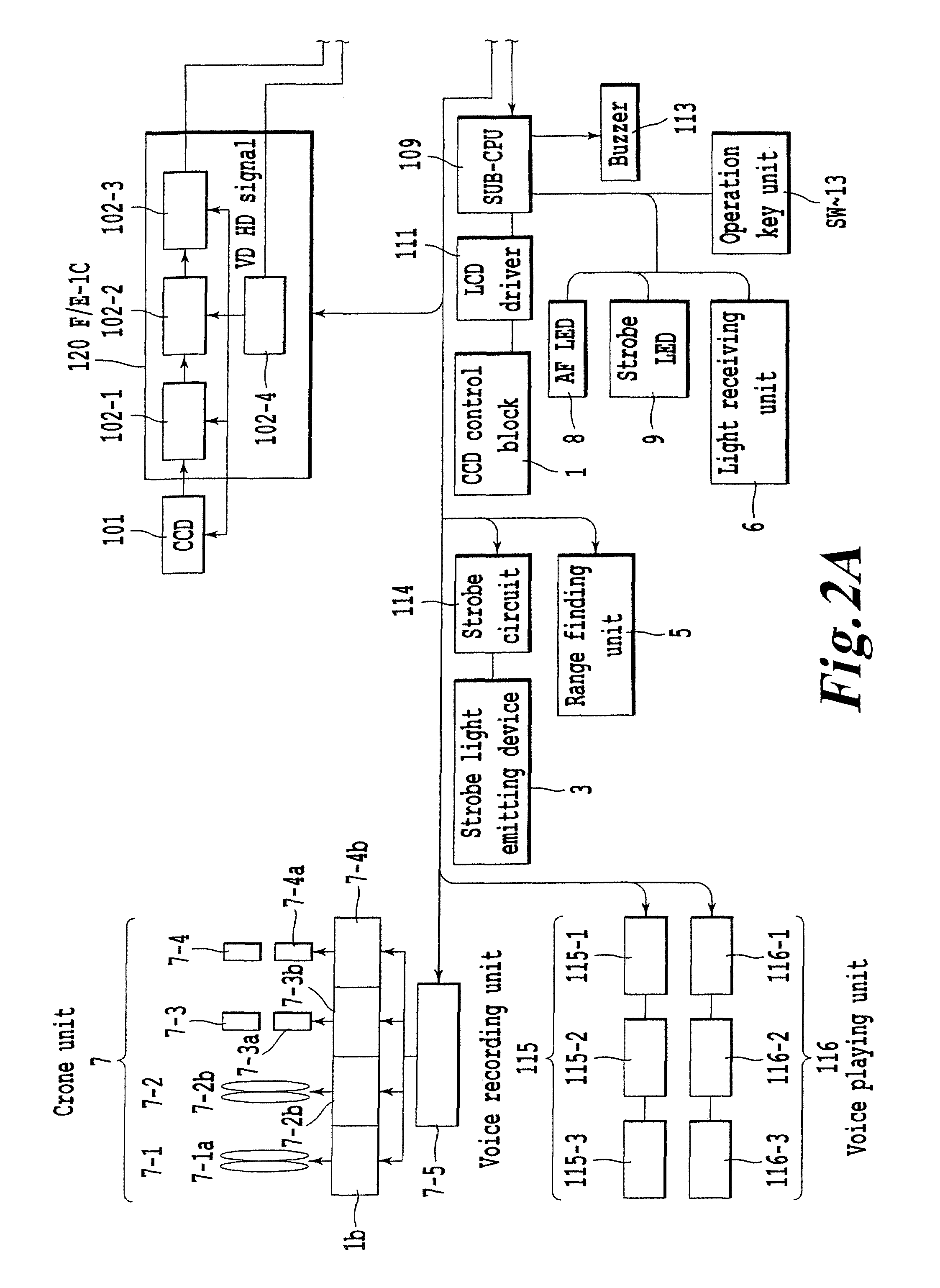
[0027]The digital camera according to the present invention comprises a camera crone unit 7 disposed in a camera body as shown in FIG. 1A to FIG. 1C. The camera crone unit 7 comprises a zoom optical system 7-1 having a zoom lens 7-1a for taking in an optical image of object and a zoom driving motor 7-1b, a focus optical system 7-2 having a focus lens 7-2a and a focus driving motor 7-2b, an aperture stop unit 7-3 having an aperture stop 7-3a and an aperture stop motor 7-3b, a mechanical shutter unit 7-4 having a mechanical shutter 7-4a and a mechanical shutter motor 7-4b, and a motor driver 7-5 for driving respective motors 7-1b to 7-4b. The motor driver 7-5 is controlled to be driven by the driving instruction from a CPU block 104-3 provided in an after-mentioned digital still camera processor 104 disposed in the camera body ...

second embodiment

[0063]In stead of measuring the elapsed time from the exposure period timing signal right after the release operation is conducted till the beginning of the exposure setup operation, as shown in FIG. 6, the elapsed time from the exposure period timing signal right after the release operation is conducted to the exposure setup operation is completed can be measured. As shown in the timing chart of FIG. 6, the elapsed time t3 from the previous VD till the setup of exposure to the F / E-IC 102 is completed is measured, and the remaining time t4 till the next VD is calculated, and then the judgment whether or not the VD reset is conducted by this calculated time t4. When the calculated time t4 is more than the predetermined time, as shown in FIG. 6, the exposure for recording can be started in the time of VD shown as the reference numeral (a′) which is output earlier than the time shown as the reference numeral (a), so that the shortening of release time lag can be achieved. The example s...

third embodiment

[0064]Next, the timing chart of FIG. 8 illustrating a third embodiment of the present invention will be described by comparing it with FIG. 7 illustrating its prior art.

[0065]FIG. 7 shows the same timing with FIG. 3 by the conventional method. The F / E-IC changes the operation mode of next exposures period by the data set up till the F / E-IC setup confirmation timing of the trailing edge of VD signal or the nearest thereof as described with reference to FIG. 3, and conducts the adjustment of exposure time by increasing and decreasing the number of horizontal synchronizing signals for the electric shutters, i.e. the number of the electric shutters. As described above, the description is given by adopting the tailing edge of VD signal as the F / E-IC setup confirmation timing.

[0066]For the prior art illustrated in FIG. 7, as shown in FIG. 3, the number of electric shutters (exposure time) for recording the still image set up by the CPU block at the processing event A are loaded inside the...


PUM


Abstract

An imaging apparatus includes an exposure period setup part for generating a timing signal, an image pick up device control part for controlling an operation of image pick up device, a timing part for measuring an elapsed time from the exposure period timing signal, and an imaging apparatus control part for controlling the image pick up device control part and the exposure period setup part. The timing part measures the elapsed time from the exposure period timing signal right after a release operation to the beginning of exposure setup operation by the exposure period setup part, and if a time from the measured elapsed time to the generation of the calculated next exposure period timing signal is equal or greater than a predetermined time, the imaging apparatus control part shortens the time till the generation of the next exposure period timing signal from a regular exposure period.

Description

BACKGROUND OF THE INVENTION[0001]1. Field of the Invention[0002]The present invention relates to an imaging apparatus, an imaging method, a program, and a recording medium, adapted to shorten a time (hereinafter referred to as a release time lag) from a time that a shutter release button is pressed for a release operation to a time that an exposure is actually started.[0003]2. Description of the Prior Art[0004]Conventionally, for a digital camera having a solid state imaging device such as a CCD, there has been proposed a technology for exposing and reading out the electric charge accumulated on the CCD by the exposure based on an external trigger signal which is asynchronous to a vertical synchronizing signal for controlling the operation of CCD (for example, see Japanese Patent Laid-Open 2000-13689). Moreover, there has been proposed a technology for generating a vertical synchronizing signal for starting an exposure period and for reading out electric charge by an external trigge...

Claims


Application Information

Patent Timeline
IPC IPC(8): G03B7/00H04N5/235H04N3/14H04N5/335H04N5/228H04N5/232H04N5/353H04N5/372
CPCH04N5/2353H04N5/232H04N23/64H04N23/73
Inventor SHIRAISHI, KENJIITO, KEI
Owner RICOH KK
Why Eureka
Try Eureka