
Assisted trace facility to improve CPU cache performance

a trace facility and cache technology, applied in the field of assisted trace facility, can solve the problems of ineffective processing of trace data, high cost of providing additional buffers, and limiting the ability of fixed number of hardware buffers to store and process trace data,

Inactive Publication Date: 2008-03-13
IBM CORP
View PDF3 Cites 26 Cited by
  • Summary
  • Abstract
  • Description
  • Claims
  • Application Information

AI Technical Summary

Benefits of technology

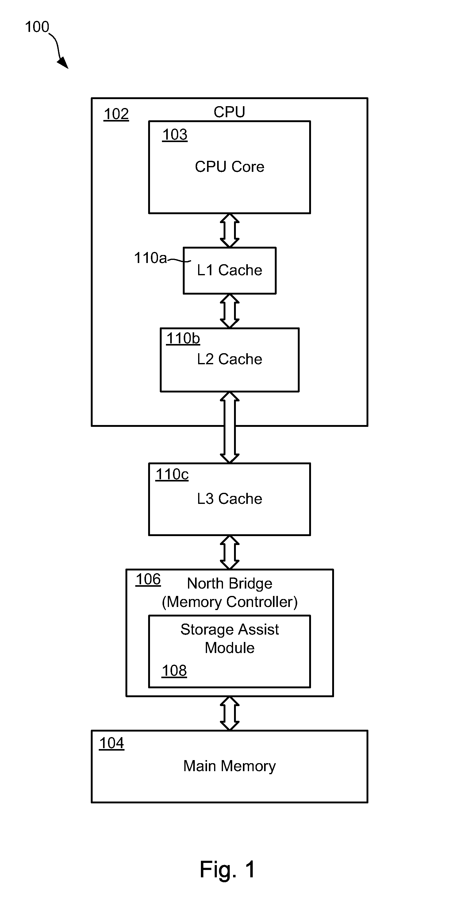
[0015]FIG. 1 is a high-level block diagram illustrating a system comprising a storage assist module in accordance with the invention; and
[00...

Problems solved by technology

Although trace data is frequently written to memory, the data is typically not read unless an event such as an error occurs.
Furthermore, although the amount of trace data stored at any specific memory location is often small, trace data is often stored at many different locations in memory.
Nevertheless, a fixed number of hardware buffers may be limiting in its ability to store and process trace data.
Furthermore, providing additional buffers is expensive and is not necessarily an effective way to process trace data.
The trace data generated by these structures has the undesirable effect of filling the L1, L2, or even L3 cache with data that is unlikely to be read.
The consequence is lower L1 and L2 hit ratios and substantially reduced processor performance.
Furthermore, performing these writes with cache-inhibited mechanisms is also unacceptable because standard microprocessors will perform such operations one word at a time on the external bus, thereby increasing system overhead significantly.

Method used


Image

  • Assisted trace facility to improve CPU cache performance
  • Assisted trace facility to improve CPU cache performance
  • Assisted trace facility to improve CPU cache performance

Examples


Embodiment Construction

[0017]It will be readily understood that the components of the present invention, as generally described and illustrated in the Figures herein, may be arranged and designed in a wide variety of different configurations. Thus, the following more detailed description of the embodiments of the systems and methods of the present invention, as represented in the Figures, is not intended to limit the scope of the invention, as claimed, but is merely representative of selected embodiments of the invention.

[0018]Some of the functional units described in this specification have been labeled as modules, in order to more particularly emphasize their implementation independence. For example, a module may be implemented as a hardware circuit comprising custom VLSI circuits or gate arrays, off-the-shelf semiconductors such as logic chips, transistors, or other discrete components. A module may also be implemented in programmable hardware devices such as field programmable gate arrays, programmabl...


PUM


Abstract

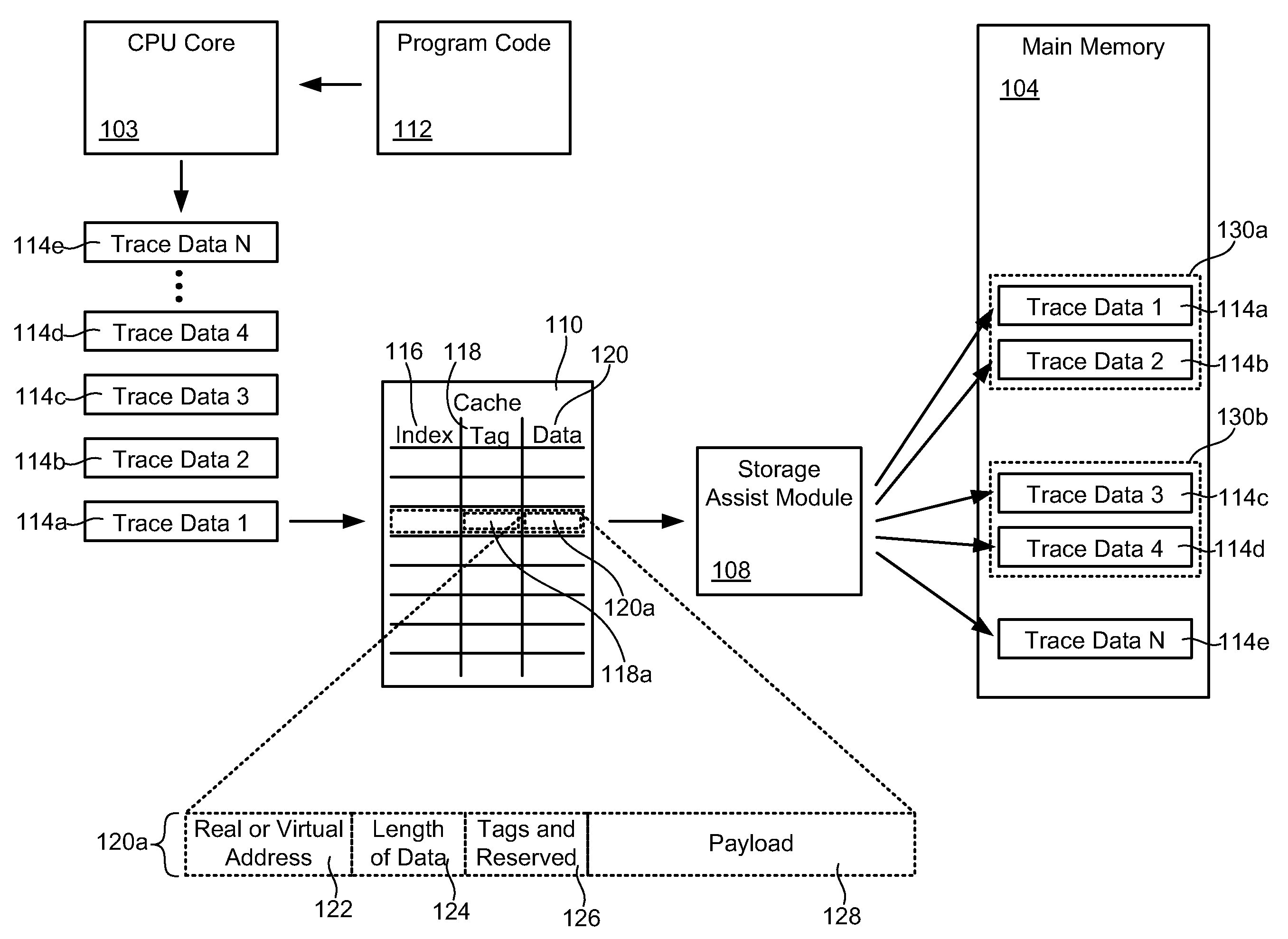
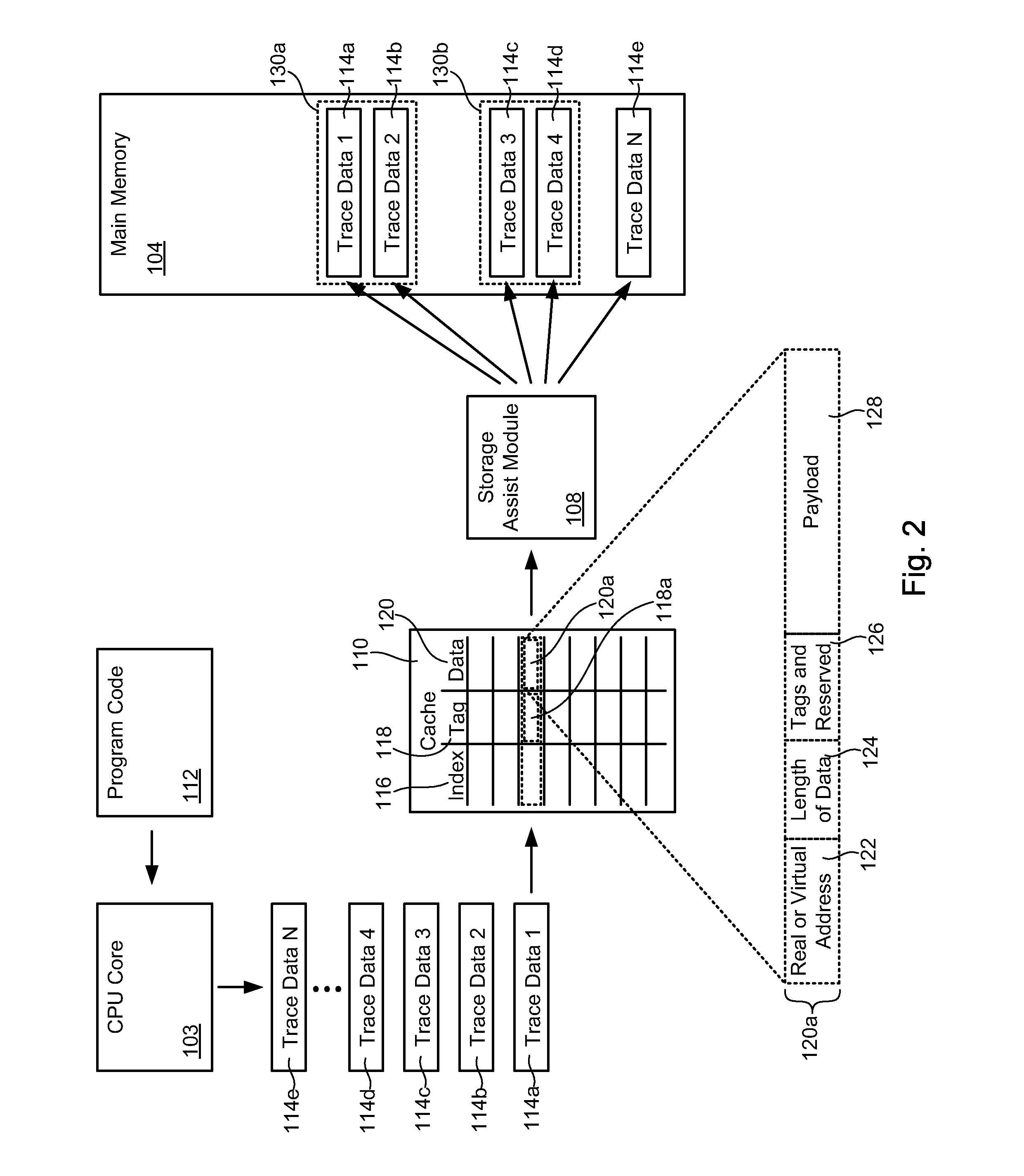
A system and method for recording trace data while conserving cache resources includes generating trace data and creating a cache line containing the trace data. The cache line is assigned a tag which corresponds to an intermediate address designated for processing the trace data. The cache line also contains embedded therein an actual address in memory for storing the trace data, which may include either a real address or a virtual address. The cache line may be received at the intermediate address and parsed to read the actual address. The trace data may then be written to a location in memory corresponding to the actual address. By routing trace data through a designated intermediate address, CPU cache may be conserved for other more important or more frequently accessed data.

Description

BACKGROUND OF THE INVENTION[0001]1. Field of the Invention[0002]This invention relates to apparatus and methods for recording trace data in computer systems and more particularly to apparatus and methods for conserving CPU cache resources when generating and recording trace data.[0003]2. Description of the Related Art[0004]Computer programs or other executables may be designed to generate and store trace data in computer memory or other storage devices. Trace data may include information about significant events that occur in the course of executing a computer program. For example, trace data may identify or include the content of memory addresses, instructions, registers, branches, exceptions, or other similar events occurring during program execution. This information is often helpful to debug or improve program code as well as to determine system behavior when a program is executing.[0005]Although trace data is frequently written to memory, the data is typically not read unless a...

Claims


Application Information

Patent Timeline
IPC IPC(8): G06F12/08G06F12/00
CPCG06F11/348G06F11/3471
Inventor SPANEL, CAROLWALLS, ANDREW DALE
Owner IBM CORP
Learn More