Downhole hydraulic control system with failsafe features

a hydraulic control system and failsafe technology, applied in the direction of valve operating means/release devices, valve/well accessories, sealing/packing, etc., can solve the problem of failsafe valve closur

Active Publication Date: 2008-03-20
BAKER HUGHES INC
View PDF10 Cites 31 Cited by
  • Summary
  • Abstract
  • Description
  • Claims
  • Application Information

AI Technical Summary

Benefits of technology

[0006]A control system for a subsurface safety valve addresses normal open and closed operation and a failsafe operation if key system components fail. It features a single control line from the surface that splits at the subsurface safety valve and goes to one end of two discrete piston chambers that are, preferably, aligned. The piston in one chamber is larger than in the other and

Problems solved by technology

Fail safe closure of the valve occ

Method used


Image

  • Downhole hydraulic control system with failsafe features
  • Downhole hydraulic control system with failsafe features

Examples


Embodiment Construction

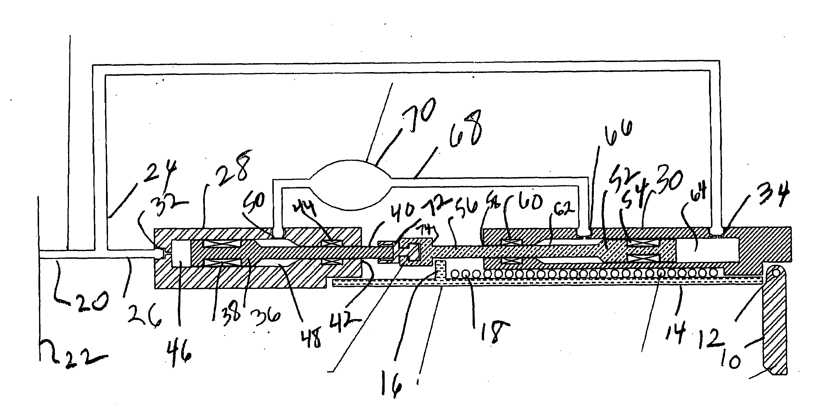
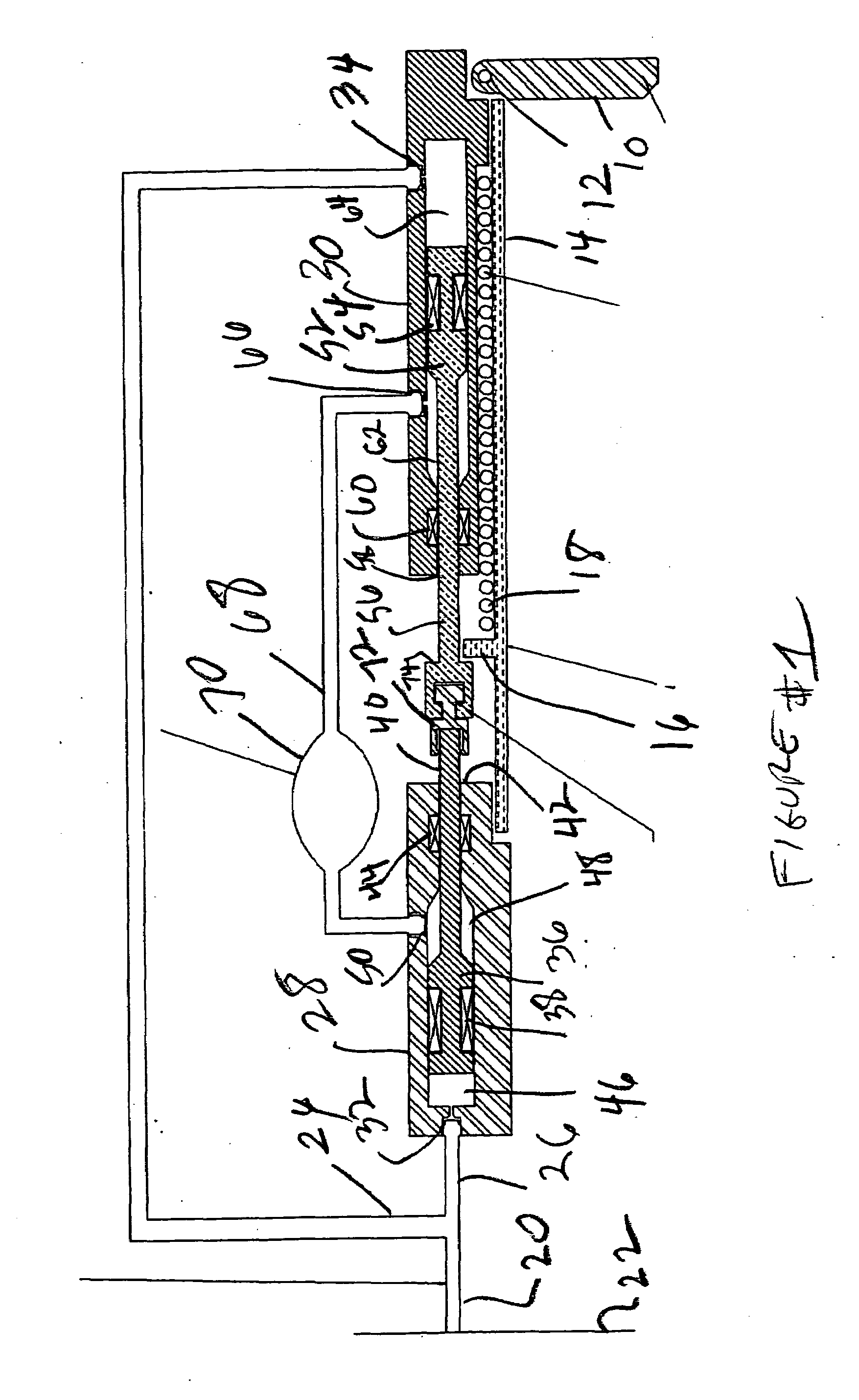
[0008]To aid in focus on the invention the subsurface safety valve will be shown schematically since the focus of the invention is on the control system that operates the valve. What is shown in FIG. 1 is the flapper 10 that pivots on a pin 12. A flow tube 14 has a tab 16 that is contacted to move the flow tube 14 against the flapper 10 to pivot it from the position shown to the open position where it is rotated 90 degrees. In the position shown, the flapper 10 is held against a complementary seat (not shown) by a spring (not shown) usually mounted on pin 12. A closure spring 18 biases tab 16 and with it the flow tube 14 away from the flapper 10 to allow the flapper to rotate 90 degrees to the closed position. Again, these schematically presented components comprise the basic elements of known subsurface safety valves and provide the context for the invention in the associated control system.

[0009]The control system's purpose is to operate the flapper 10 between its closed position ...


PUM


Abstract

A control system for a subsurface safety valve addresses normal open and closed operation and a failsafe operation if key system components fail. It features a single control line from the surface that splits at the subsurface safety valve and goes to one end of two discrete piston chambers that are aligned and isolated from tubing pressure. The piston in one chamber is larger than in the other and the pistons are connected for tandem movement. Each side of the unbalanced system's piston has a seal mounted to it and another for the rod attached to it that exits the chamber. A jumper line connects the chambers at a point between the seals in each chamber and features a large reservoir. The jumper line is filled with a compressible fluid. Fail safe closure of the valve occurs if any of the four seals fail.

Description

FIELD OF THE INVENTION[0001]The field of this invention is tubing pressure insensitive control systems for downhole tools such as subsurface safety valves, ball valves, sliding sleeves or packoff tubing hangers, for example, and more particularly features of such systems that allow a safety valve to go to a failsafe mode in the event of component malfunction.BACKGROUND OF THE INVENTION[0002]Subsurface safety valves are used in wells to close them off in the event of an uncontrolled condition to ensure the safety of surface personnel and prevent property damage and pollution. Typically these valves comprise a flapper, which is the closure element and is pivotally mounted to rotate 90 degrees between an open and a closed position. A hollow tube called a flow tube is actuated downwardly against the flapper to rotate it to a position behind the tube and off its seat. That is the open position. When the flow tube is retracted the flapper is urged by a spring mounted to its pivot rod to r...

Claims


Application Information

Patent Timeline
IPC IPC(8): E21B34/00
CPCE21B34/10E21B23/065
Inventor BANE, DARREN E.ANDERSON, DAVID Z.JACKSON, AARON T.BEALL, CLIFFORD H.WELCH, EDWARD W.WAGNER, ALAN N.
Owner BAKER HUGHES INC
Why Eureka
Try Eureka