Stopcock With Swabbable Valve

Inactive Publication Date: 2008-03-20
HALKEY ROBERTS CORP
View PDF16 Cites 71 Cited by
  • Summary
  • Abstract
  • Description
  • Claims
  • Application Information

AI Technical Summary

Problems solved by technology

Unfortunately, most current swabbable valves restrict free flow of passing fluid by employing narrow passages, ribs or internal cannula-like features.
Restricting the flow path in such a manner may create conditions for hemolytic damage.
Such restrictions also make the valve generally more difficult to flush.
However, often the instrument used to inject or withdraw the fluid (which is generally the male component of the sy

Method used


Image

  • Stopcock With Swabbable Valve
  • Stopcock With Swabbable Valve
  • Stopcock With Swabbable Valve

Examples


Embodiment Construction

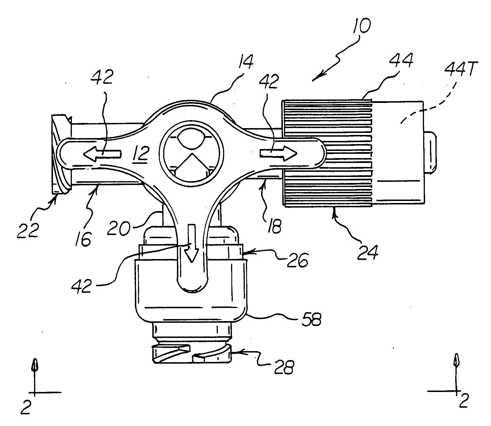
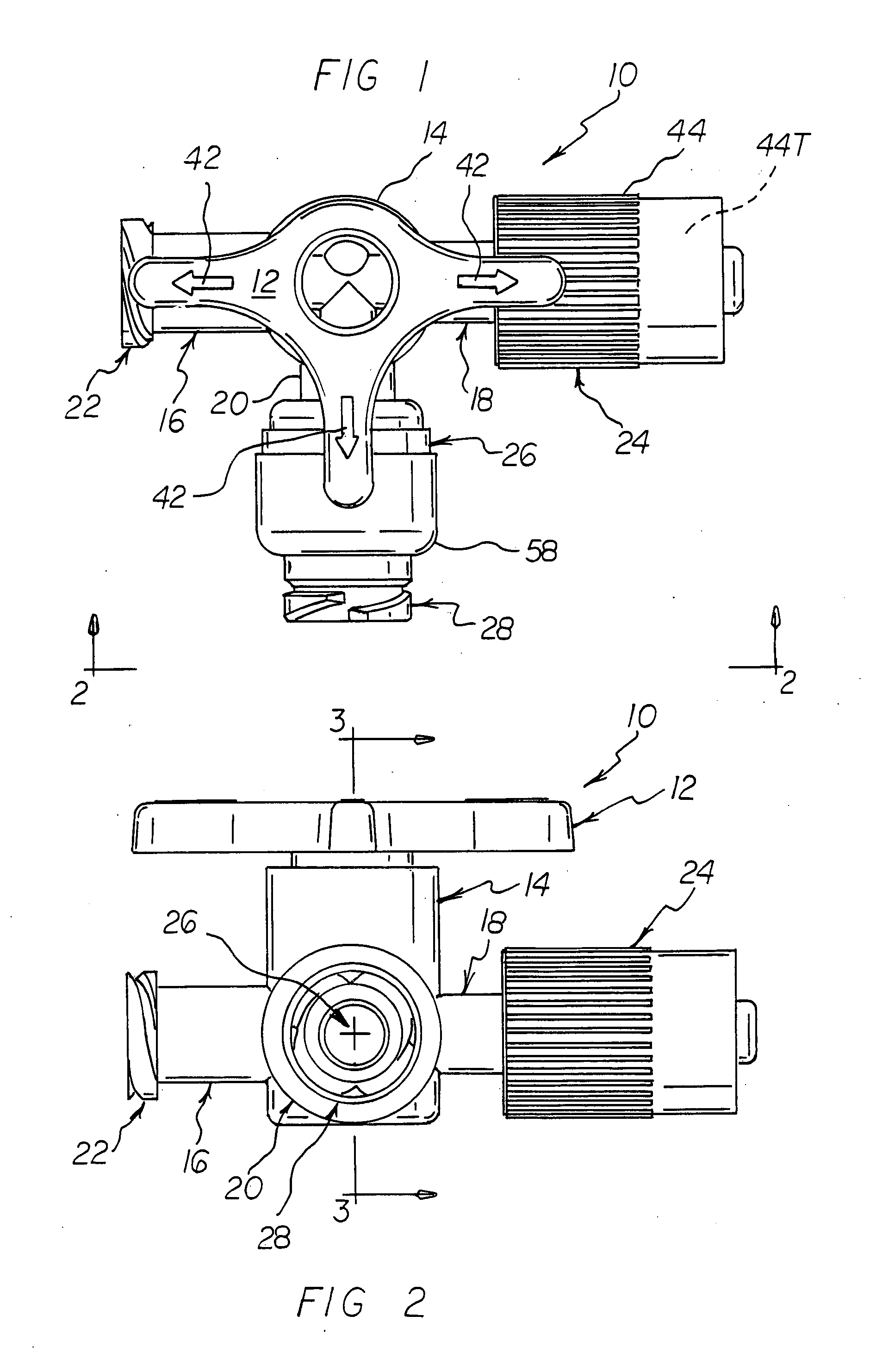
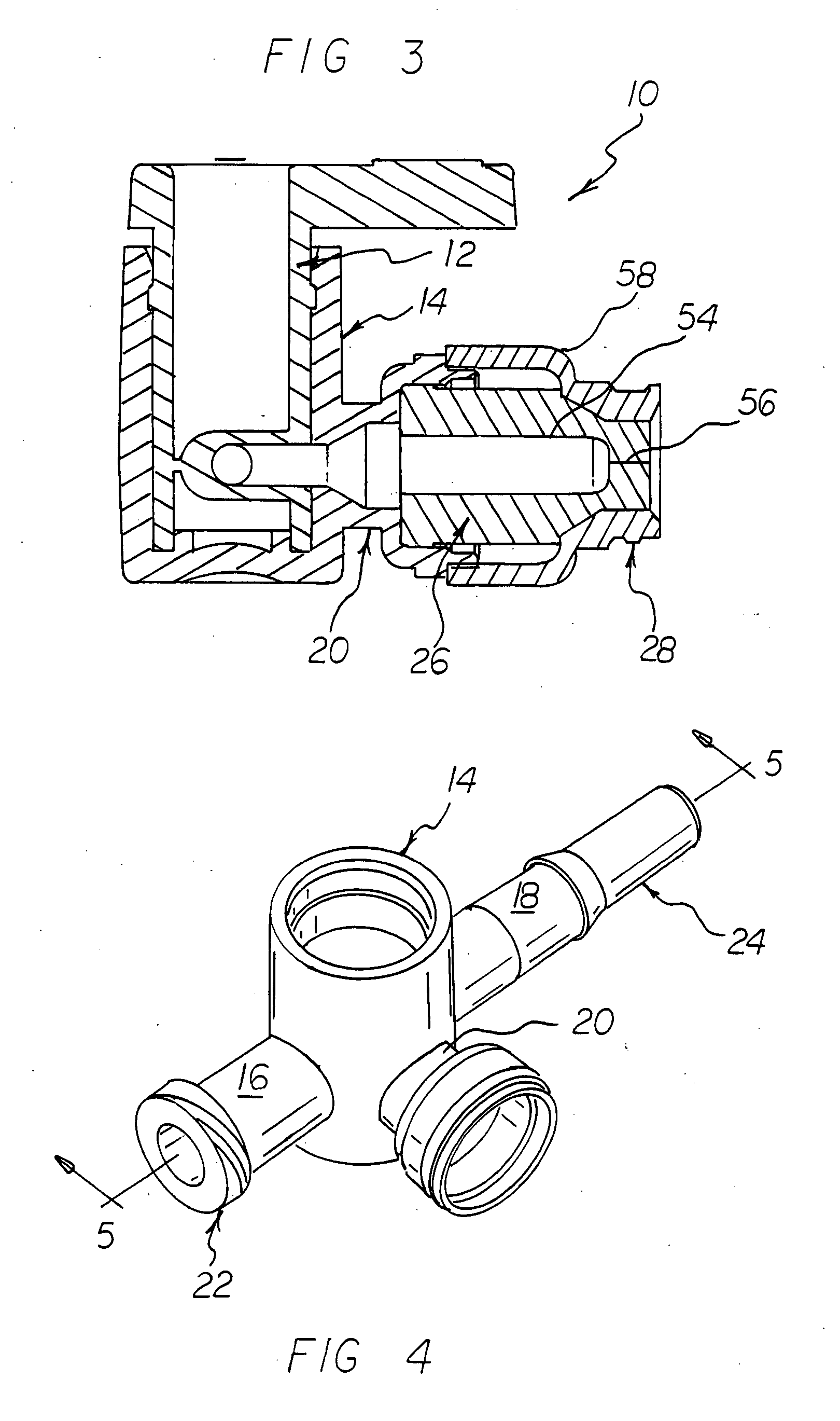
[0037] As shown in the FIGS. 1-3, the swabbable stopcock 10 of the invention comprises a stopcock valve element 12 that controls the flow of fluid through a main valve body 14 having at least two inlets, preferably three, 16, 18 and 20 (see also FIGS. 4 and 5). One of the inlets 16, 18 or 20 (e.g., inlet 16) is fitted with a conventional female luer fitting 22. Another one of the inlets 16, 18 and 20 (e.g., inlet 18) is fitted with a male luer fitting 24. Still another one of the inlets 16, 18 and 20 (e.g., inlet 20) is fitted with a swabbable valve 26 having a luer fitting 28. Preferably, the female / male luer inlets 16 and 18 are positioned in-line and the inlet 20 comprising the swabbable valve 26 is positioned transversely therebetween. The stopcock 10 may be connected in-line with an IV line via the respective female & male luer fittings 22 and 24 of the in-line inlets 16 and 18. With the swabbable valve 26 of the middle inlet 20 comprising a normally-closed valve, the arrangeme...


PUM


Abstract

A stopcock for connection in-line with a fluid line including a main valve body main having at least a plurality of inlets, including a stopcock valve element positioned within the main valve body that controls the flow of fluid through the inlets and a swabbable valve fitted to one of the inlets.

Description

CROSS-REFERENCE TO RELATED INVENTIONS [0001] This application claims the benefit of provisional application number 60 / 836,598, filed Aug. 9, 2006, the disclosure of which is hereby incorporated by reference herein.BACKGROUND OF THE INVENTION [0002] 1. Field of the Invention [0003] This invention relates to valves. More particularly, this invention relates to swabbable valves used in the medical industry. [0004] 2. Description of the Background Art [0005] As the term implies, the term “swabbable” is often used in conjunction with medical valves having a female luer fitting configured in such a way that allows swabbing of the exposed portion of the valve just prior to connection with a male luer needleless syringe or other device. [0006] Representative swabbable valves are disclosed in U.S. Pat. Nos. 6,036,171, 6,692,478, 6,221,065, 6,168,137, 6,117,114, 6,651,956, 6,113,068 and RE37,357, the disclosures of each of which are hereby incorporated by reference herein. [0007] As taught by...

Claims


Application Information

Patent Timeline
IPC IPC(8): A61M39/22
CPCA61M39/16A61M2039/229A61M39/26A61M39/22
Inventor MILLER, PAVEL T.ROGIER, STEPHEN J.
Owner HALKEY ROBERTS CORP
Why Eureka
Try Eureka