Fluid delivery system with high and low pressure hand manifold

a technology of hand manifold and fluid delivery system, which is applied in the direction of pump control, intravenous device, other medical devices, etc., can solve the problem that the effort of the operator often leads to fatigu

a technology of hand manifold and fluid delivery system, which is applied in the direction of pump control, intravenous device, other medical devices, etc., can solve the problem that the effort of the operator often leads to fatigu

US9259527B2Active Publication Date: 2016-02-16BAYER HEALTHCARE LLC

Image

  • Fluid delivery system with high and low pressure hand manifold
  • Fluid delivery system with high and low pressure hand manifold
  • Fluid delivery system with high and low pressure hand manifold

Examples


Embodiment Construction

[0032]For purposes of the description hereinafter, spatial orientation terms, as used, shall relate to the referenced embodiment as it is oriented in the accompanying drawing figures or otherwise described in the following detailed description. However, it is to be understood that the embodiments described hereinafter may assume many alternative variations and configurations. It is also to be understood that the specific components, devices, features, and operational sequences illustrated in the accompanying drawing figures and described herein are simply exemplary and should not be considered as limiting.

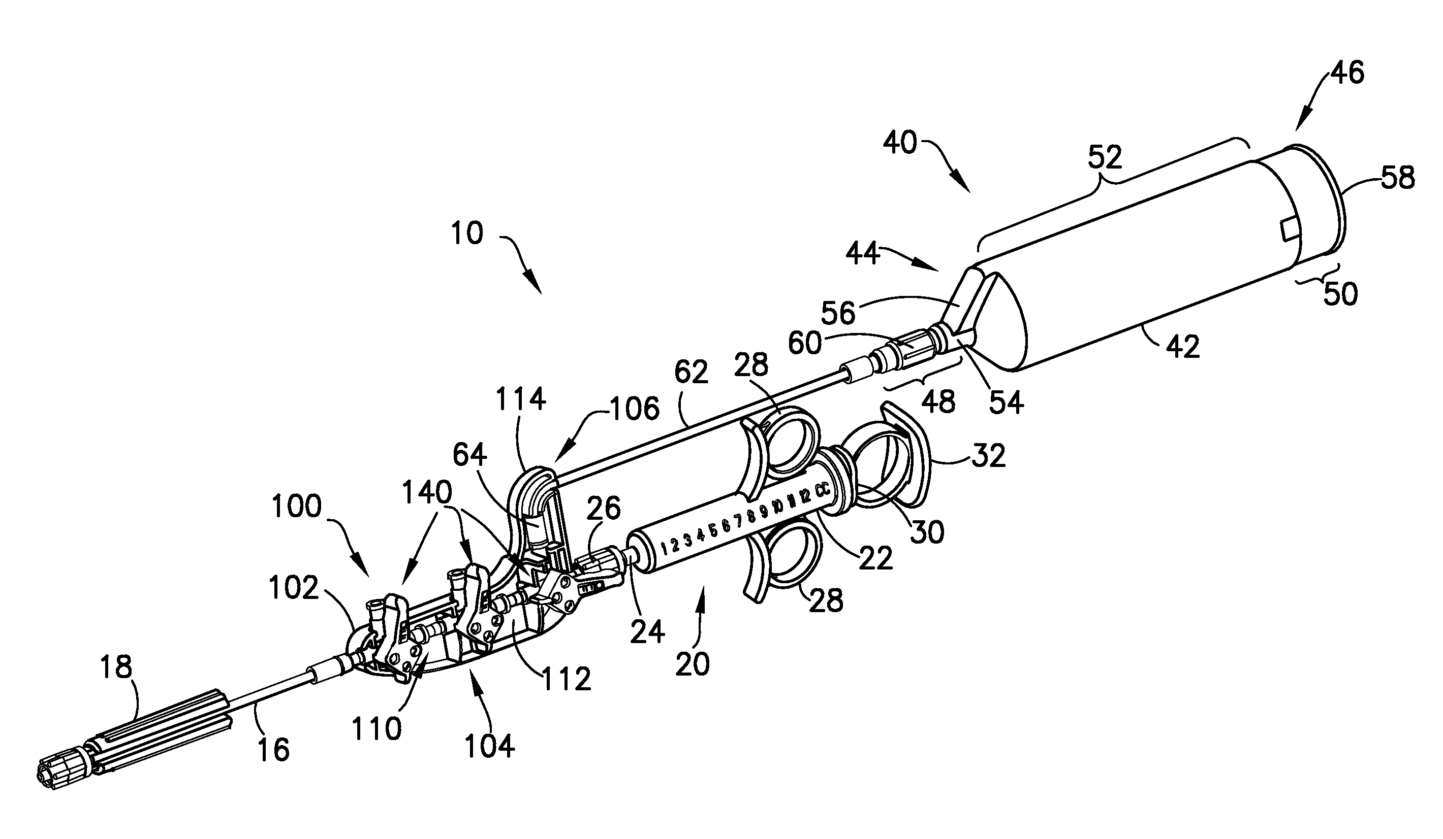
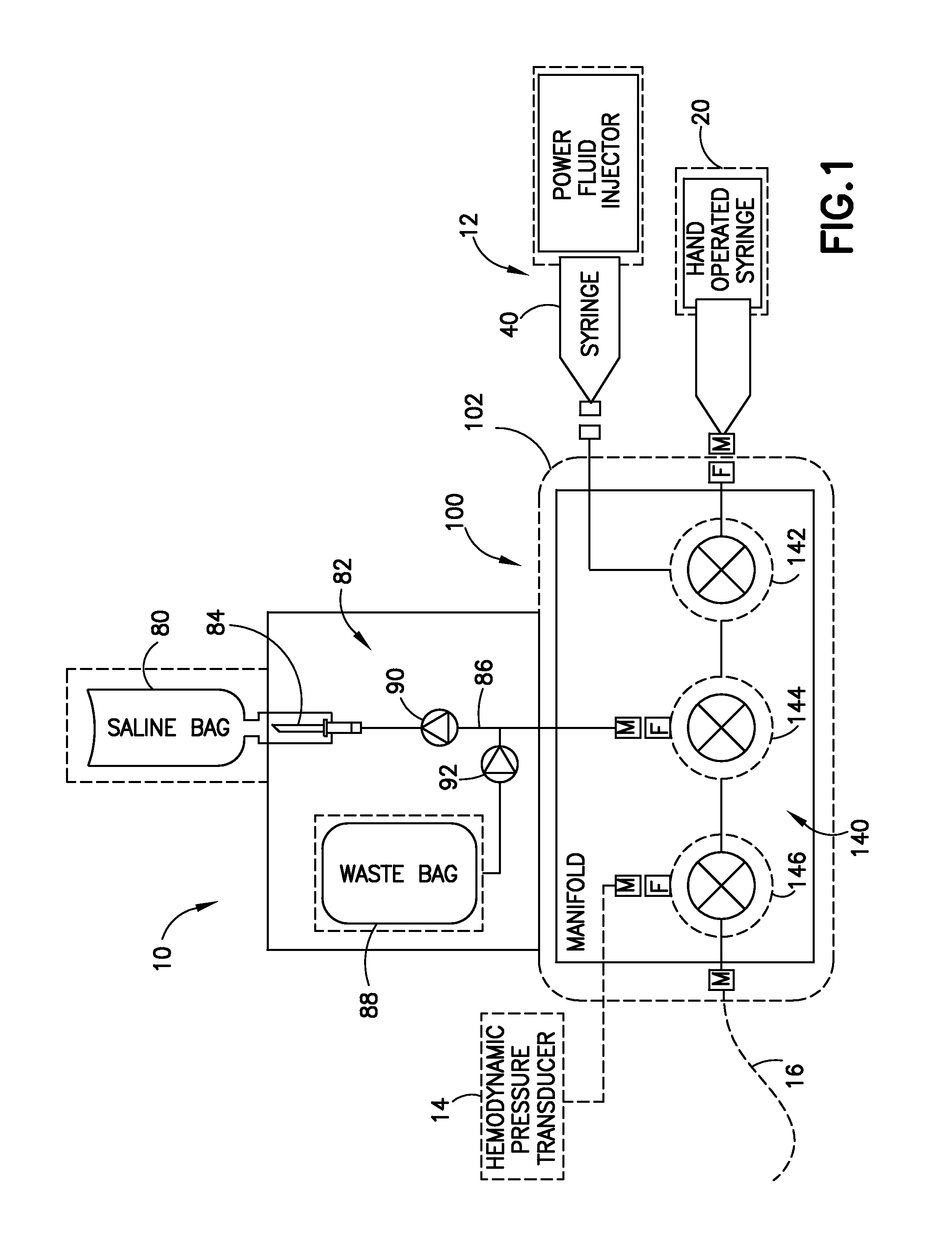
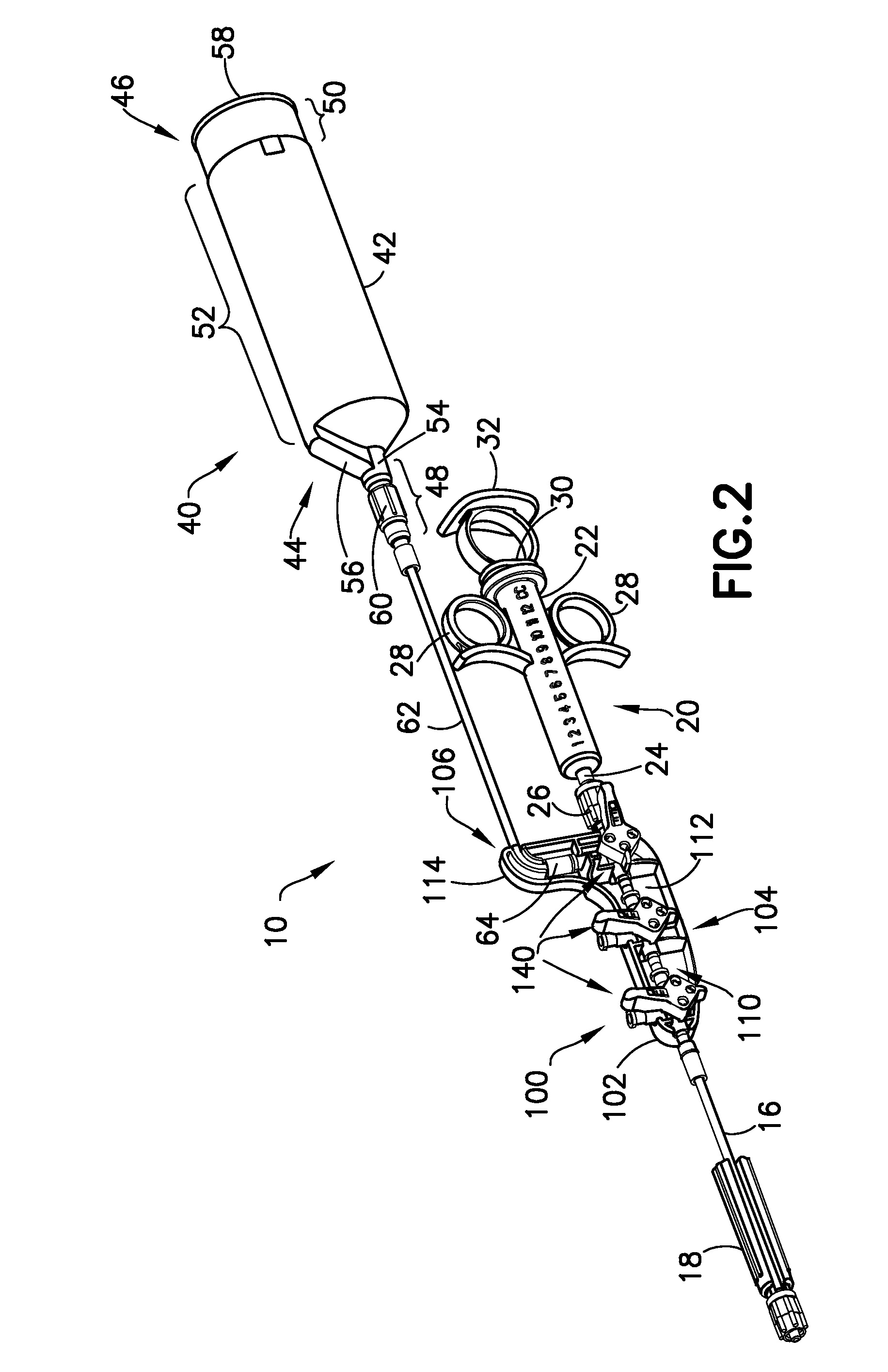
[0033]Referring to FIG. 1, a fluid delivery system 10 is shown and includes a dual high and lower pressure hand manifold 100 adapted for fluid connection to a plurality of fluid sources. The fluid sources may include a low pressure, hand-operated syringe 20, a high pressure, power injector operated syringe 40, and one or more additional fluid sources or containers such as fluid sou...


PUM


Abstract

A fluid delivery system is provided and includes a power injector supporting a high pressure syringe. The fluid delivery system further includes a manifold and a low pressure hand-operated syringe. The manifold generally includes a plurality of fluid control valves in series fluid communication. A first fluid control valve of the plurality of fluid control valves has a first port, a second inlet port, and a third port. The third port of the first fluid control valve is in fluid connection with a first port of a second fluid control valve. The low pressure hand-operated syringe is in fluid connection with the first port of the first fluid control valve, and the high pressure syringe is in fluid connection with the second port of the first fluid control valve. The fluid control valves may be multi-position stopcock valves.

Description

CROSS-REFERENCE TO RELATED APPLICATIONS[0001]This application claims the benefit of U.S. Provisional Application No. 61 / 714,872, filed Oct. 17, 2012.BACKGROUND OF THE INVENTION[0002]1. Field of the Invention[0003]This disclosure relates to medical fluid delivery applications and, particularly, a fluid delivery system comprising a fluid path set with a high and low pressure hand manifold for delivery of one or more medical fluids to a patient undergoing a medical diagnostic or therapeutic procedure.[0004]2. Description of Related Art[0005]In many medical diagnostic and therapeutic procedures, a medical practitioner such as a physician injects a patient with a fluid. In recent years, a number of injector-actuated syringes and powered injectors for pressurized injection of fluids, such as contrast media (often referred to simply as “contrast”, have been developed for use in procedures such as angiography, computed tomography (CT), ultrasound, and NMR / MRI. In general, these powered inje...

Claims


Application Information

Patent Timeline
16 Feb 2016
Publication
US9259527B2
IPC
A61M5/00; A61M5/14; A61M39/22
CPC
A61M5/007; A61M5/1408; A61M39/223; A61M2039/229; A61M2039/242; A61M2039/0027; F04C2270/041; A61M39/00
Inventors
SPOHN, MICHAEL A; SWANTNER, MICHAEL JAMES