Random rebound practice device

a random rebound and practice device technology, applied in dartboards, sports equipment, weapons, etc., can solve the problems of limited usefulness of random rebound structures, less lightweight and portable devices, and inability to easily deform into more compact forms

Inactive Publication Date: 2008-03-20
WILSON HUNT INT
View PDF15 Cites 41 Cited by
  • Summary
  • Abstract
  • Description
  • Claims
  • Application Information

AI Technical Summary

Benefits of technology

[0006]According to a first aspect of the present invention, a random rebound practice device is provided which includes a support attached to a target panel. The support is formed of one or more support panels that each includes a rebound net secured thereto that extends from the respective support panel onto the target panel. On the target panel, each of the net structures are secured to the target panel and offset slightly from one another on the target panel. The offset of the net structures enables the net structures to function similarly to a rebound net. However, instead of simply rebounding a projectile or ball back to an individual utilizing the device, the offset net structures redirect the projectile off of the target panel in a random manner.

Problems solved by technology

These types of materials are not easily deformed into more compact forms, such that to store the rebound surfaces the surfaces formed of these materials must often be disassembled for storage, instead of being folded similar to simple rebound nets.
In addition, due to the different requirements for mounting these heavier random rebound surfaces to form the practice device, the type of frames supporting these surfaces necessarily have to be constructed differently from the conventional frames utilized to hold rebound nets, making the devices less lightweight and portable as a result.
Thus, while providing more realistic game play than prior rebound devices, the random rebound structures are limited in their usefulness due to their portability and storage limitations.

Method used


Image

  • Random rebound practice device
  • Random rebound practice device
  • Random rebound practice device

Examples


Embodiment Construction

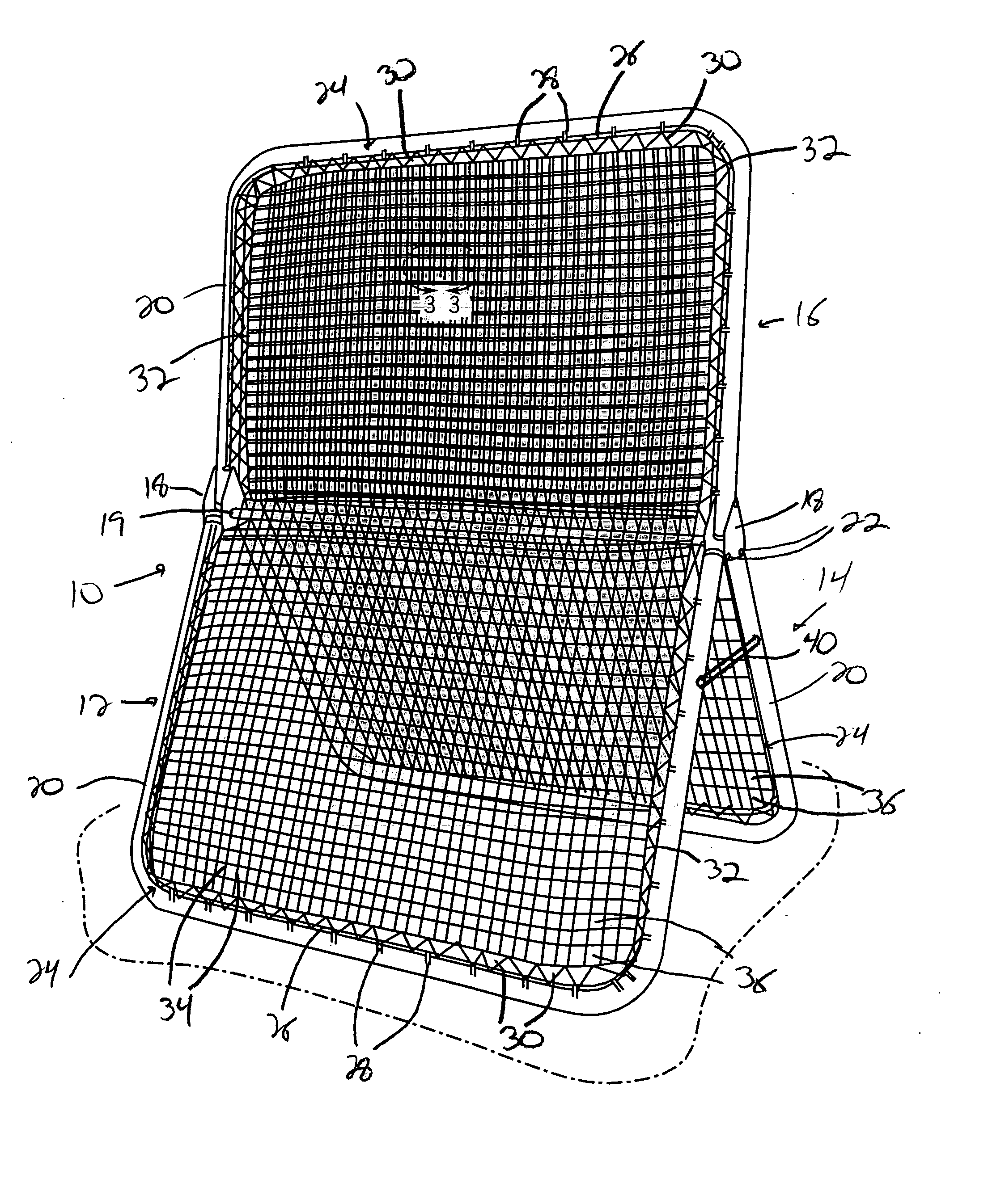
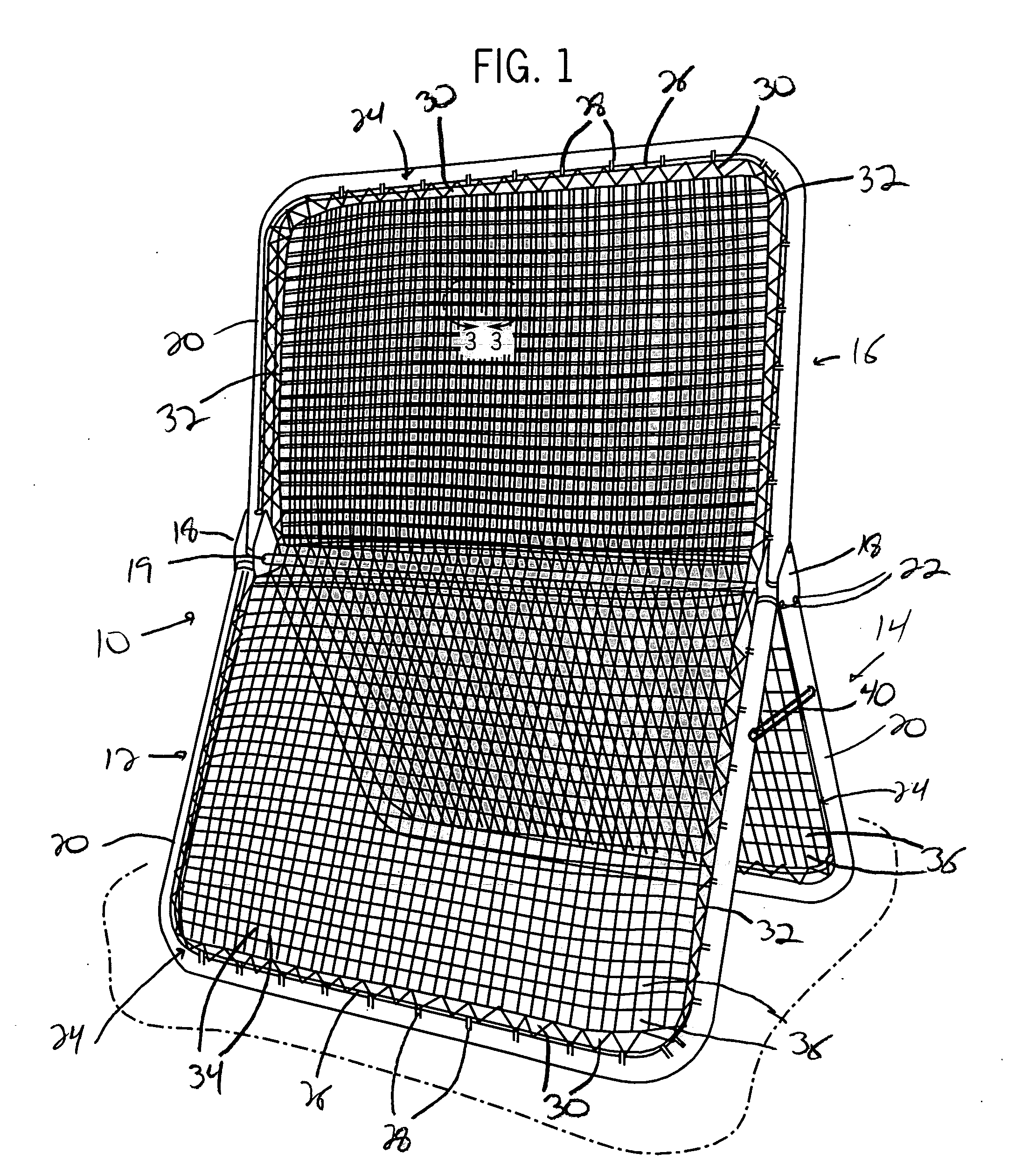
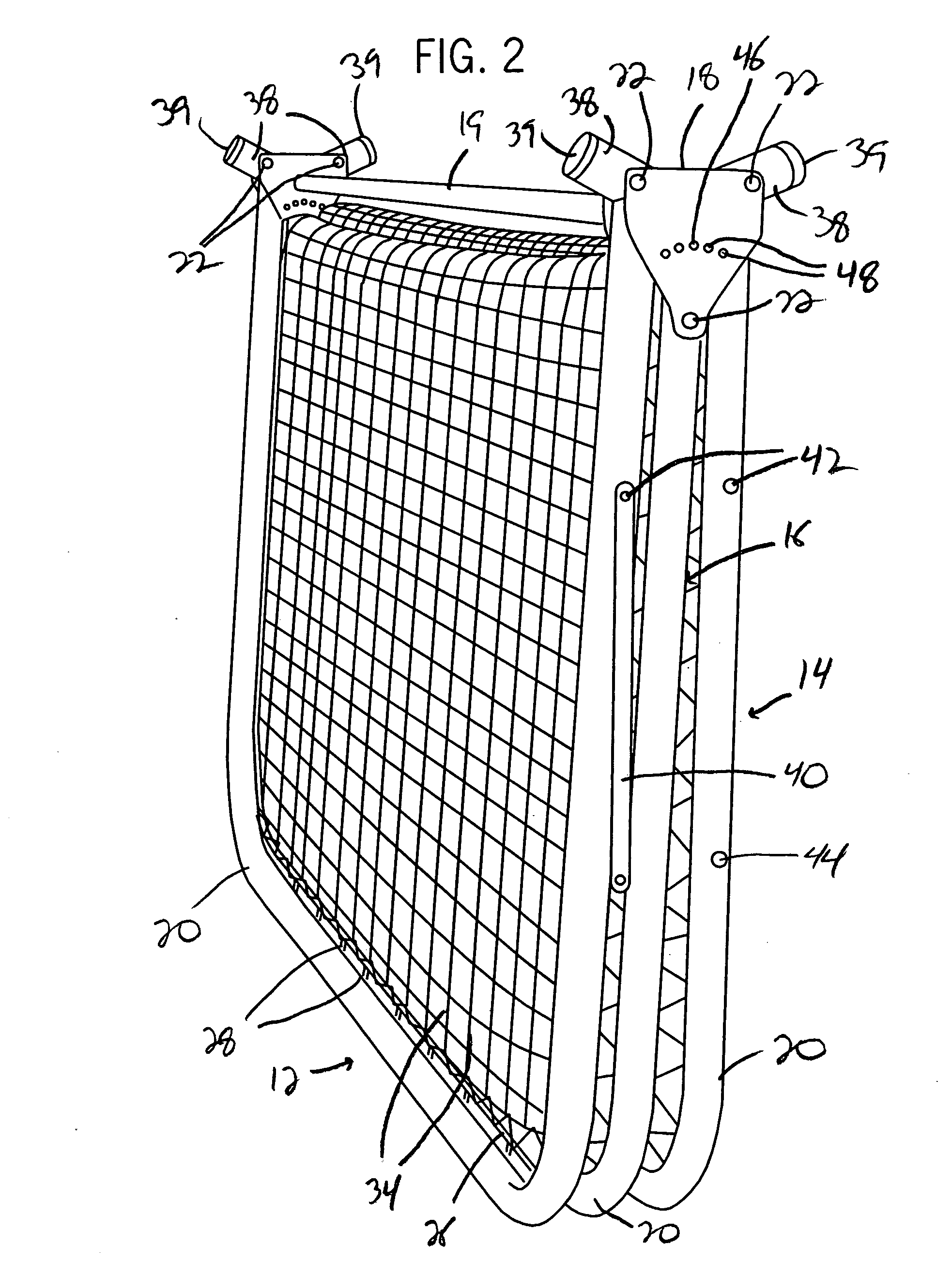
[0018]With reference now to the drawing figures in which like reference numerals designate like parts throughout the disclosure, a random rebound practice device constructed according to the present invention as indicated generally at 10 at FIG. 1. In the preferred, illustrated embodiment, the device 10 includes a pair of support panels 12 and 14 connected to a target panel 16. The shape of the support panels 12 and 14 and the target panel 16 can have any desired configuration, but in the preferred embodiment, the panels 12-16 are each generally rectangular in shape and are each connected at one end to a pair of brackets 18.

[0019]The support panels 12 and 14 each are formed with a U-shaped, tubular frame 20 that is formed of a rigid material, such as a metal or hard plastic. The frame 20 for each panel 12 and 14 is pivotally secured at opposite ends to each of a pair of bracket 18 through the use of a suitable fastener or pivot pin 22 fixedly attached to each of the brackets 18 and ...


PUM


Abstract

A random rebound sports training device is provided which includes a pair of misaligned or offset net structures disposed on a frame that enable a projectile striking the net structures to rebound in a random manner. The structures are secured to a support frame such that the openings formed in the net structure, which are larger than normally utilized, are offset from one another. The offset of each of the net structures greatly reduces the potential for a projectile striking the device from contacting the same portions of the net structures, thereby causing the projectile to rebound in a random manner from the device. The frame on which the net structures are mounted can be easily configured between a use configuration and a storage configuration. Further, each of the net structures can be secured to a single support frame, or can extend from separate frames onto a target frame to provide multiple use sections on the device.

Description

FIELD OF THE INVENTION[0001]The present invention relates to sporting equipment, and more specifically to a rebound practice device utilized to practice games requiring balls or other projectiles to be thrown or caught by an individual.BACKGROUND OF THE INVENTION[0002]To enable individuals to practice various sports involving the throwing of a projectile, such as a ball, at a specified target, such as another player, a number of different practice devices have been developed. The majority of these devices include a target having a rebound component or net which directs the projectile thrown by the individual against the target back to the individual after striking the target.[0003]To enhance the realistic, live action game qualities of the practice targets of this type, a number of different devices have been developed which allow the device to rebound or redirect the projectile back to the individual in an unpredictable, or random, manner. These devices, instead of having a net, us...

Claims


Application Information

Patent Timeline
Patent Type & Authority Applications(United States)
IPC IPC(8): A63B63/00
CPCA63B63/00A63B2210/50A63B69/0097A63B63/007
Inventor HUNT, RYAN
Owner WILSON HUNT INT
Why Eureka
Try Eureka