

Surface light source, method of driving the same, and backlight unit having the same
- Summary
- Abstract
- Description
- Claims
- Application Information
AI Technical Summary
Benefits of technology
Problems solved by technology
Method used
Image

Examples
Embodiment Construction
[0033] The present invention will now be described more fully hereinafter with reference to the accompanying drawings, in which preferred embodiments of the invention are shown.
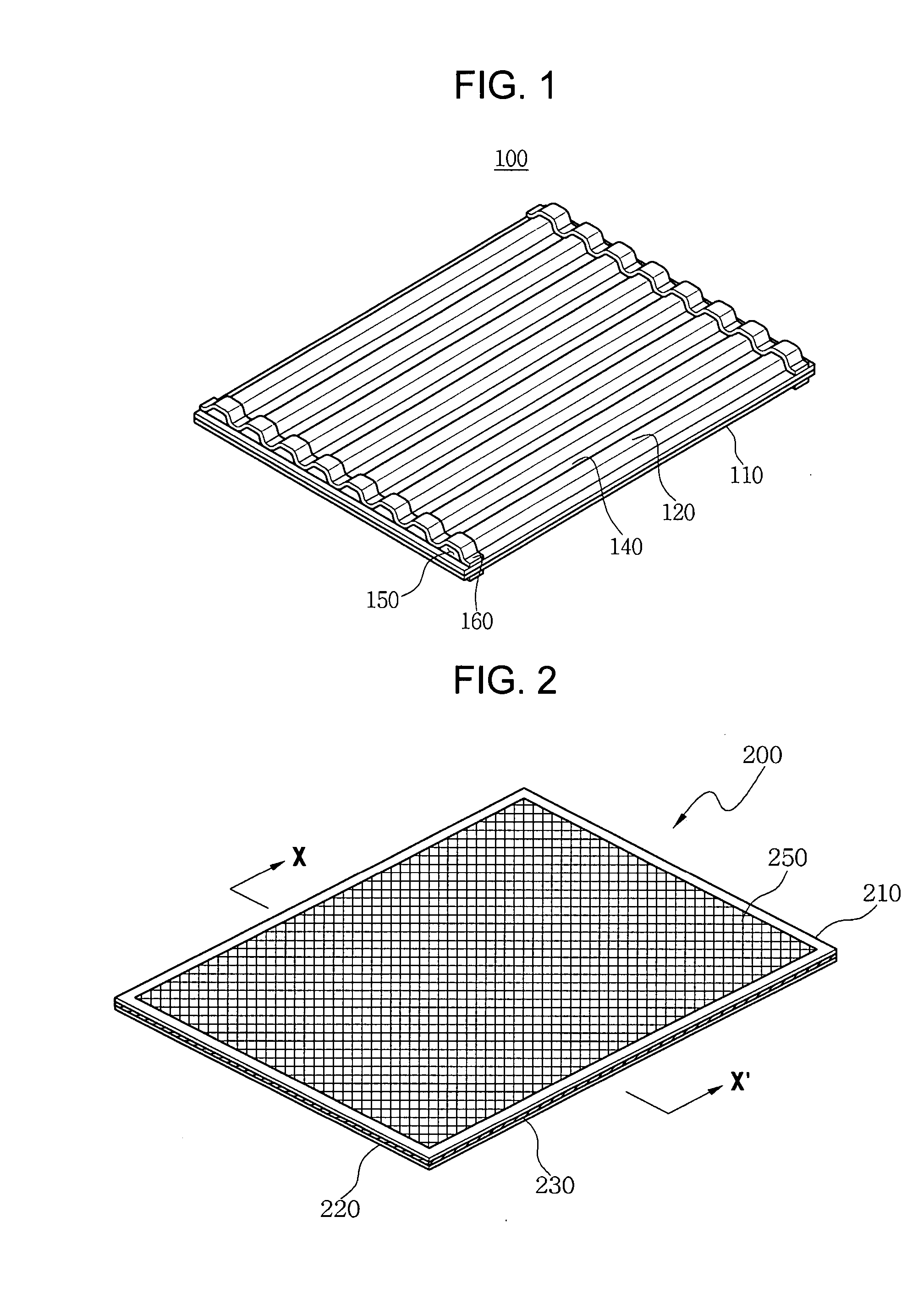
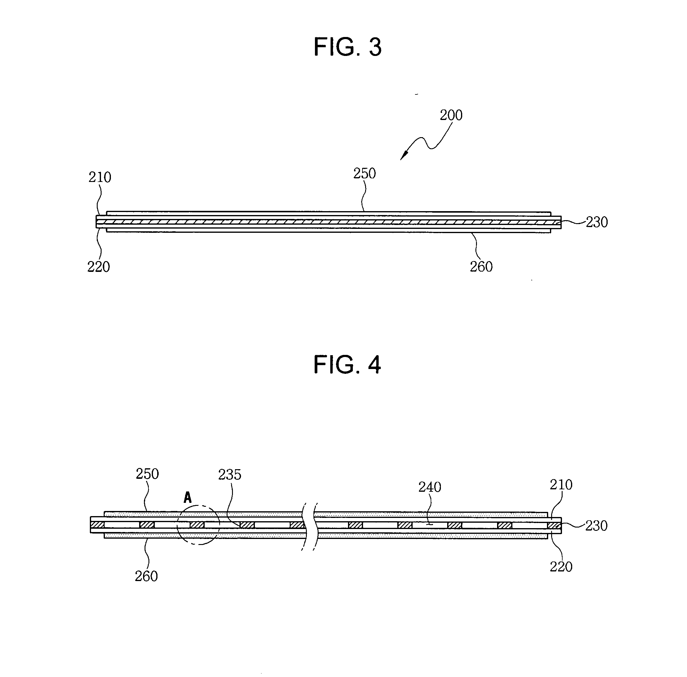
[0034]FIG. 2 is a perspective view illustrating a surface light source 200 according to an embodiment of the present invention, and FIG. 3 is a side view of the surface light source 200.
[0035] The surface light source 200 includes a plate type first substrate 210 and a same type second substrate 220. The first substrate 210 and the second substrate 220 are preferably made of transparent thin glass substrate, and have no restriction for thickness, but may have a thickness of about 1 mm to 2 mm, preferably, less than 1 mm.
[0036] A fluorescent layer is coated on the inner sides of the first and second substrates 210 and 220, and a reflective layer may be further formed on any one of the first and second substrates 210 and 220. The first substrate 210 and the second substrate 220 face each other by a predeterm...
PUM
 Abstract
Description
Claims
Application Information