
Surface light source, method of driving the same, and backlight unit having the same

a technology of surface light source and backlight unit, which is applied in the direction of instruments, discharge tubes, luminescent screens, etc., can solve the problems of low brightness, poor brightness, and high power consumption of led, and achieve clearer and more natural images.

Inactive Publication Date: 2012-05-15
SAMSUNG CORNING PRECISION MATERIALS CO LTD
View PDF8 Cites 6 Cited by
  • Summary
  • Abstract
  • Description
  • Claims
  • Application Information

AI Technical Summary

Benefits of technology

[0011]In order to improve image quality of the liquid crystal display and to implement a more clean and natural image, a technology is provided for simultaneously varying the brightness of individual regions of the surface light source.
[0017]In the surface light source and the backlight unit according to one embodiment of the present invention, the electrode unit is partitioned into plural regions and voltages are applied to respective regions so that brightness of each region can be independently controlled. In this way, local dimming of the surface light source can be provided in accordance with screen information of the liquid crystal display to enable a clearer and more natural image to be obtained.

Problems solved by technology

On the other hand, The LED has high power consumption, but has excellent brightness.
Liquid crystal displays having a CCFL or an LED tend to suffer from nonuniform brightness.
However, the optical members significantly increase the size and weight of a liquid crystal display employing the aforementioned CCFL or LED.

Method used


Image

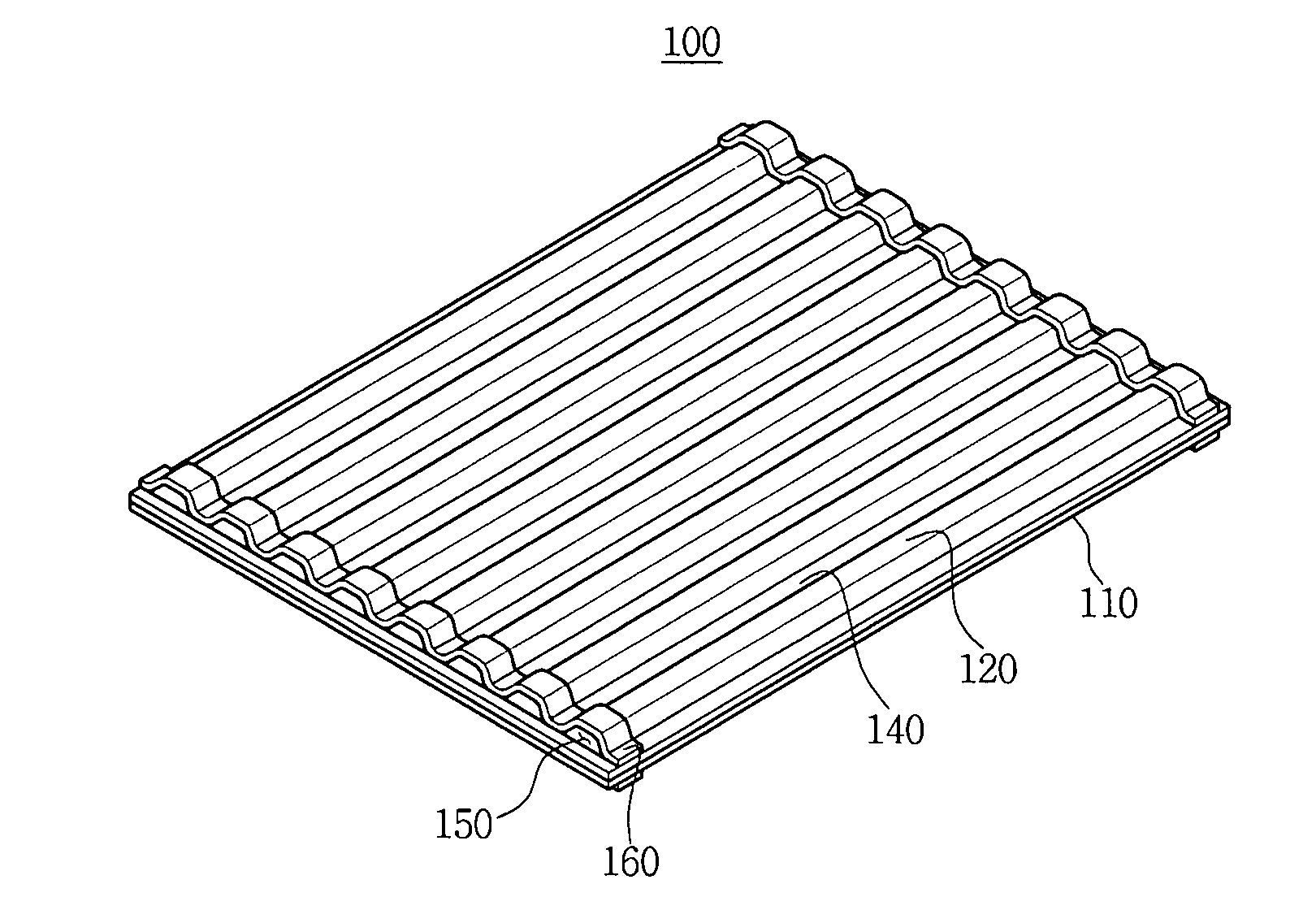
  • Surface light source, method of driving the same, and backlight unit having the same
  • Surface light source, method of driving the same, and backlight unit having the same
  • Surface light source, method of driving the same, and backlight unit having the same

Examples


Embodiment Construction

[0033]The present invention will now be described more fully hereinafter with reference to the accompanying drawings, in which preferred embodiments of the invention are shown.

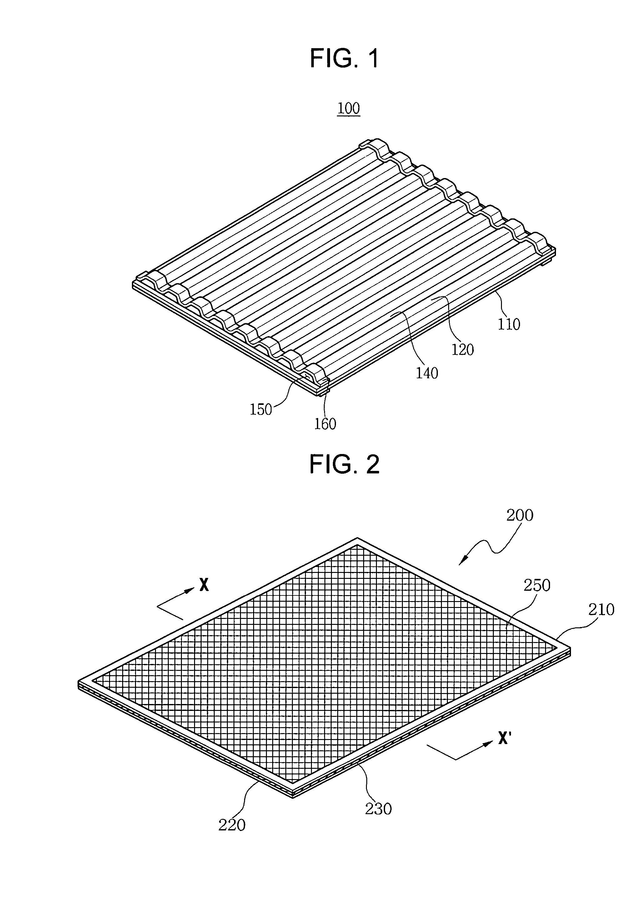
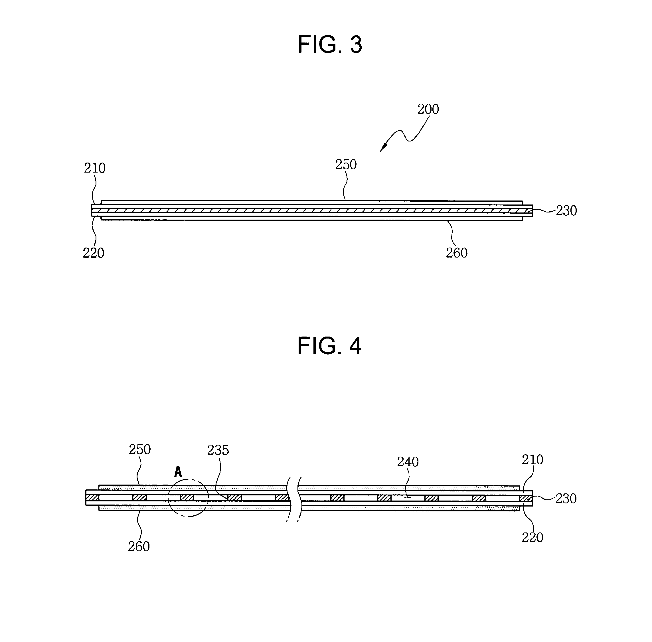
[0034]FIG. 2 is a perspective view illustrating a surface light source 200 according to an embodiment of the present invention, and FIG. 3 is a side view of the surface light source 200.

[0035]The surface light source 200 includes a plate type first substrate 210 and a same type second substrate 220. The first substrate 210 and the second substrate 220 are preferably made of transparent thin glass substrate, and have no restriction for thickness, but may have a thickness of about 1 mm to 2 mm, preferably, less than 1 mm.

[0036]A fluorescent layer is coated on the inner sides of the first and second substrates 210 and 220, and a reflective layer may be further formed on any one of the first and second substrates 210 and 220. The first substrate 210 and the second substrate 220 face each other by a predetermined d...


PUM


Abstract

A surface light source includes a plate type light source body having a sealed discharging space formed therein, a plate type electrode unit having a plurality of regions adjacent to at least one major surface of the light source body, and a multiple voltage applying unit operable to apply voltages independently to each of the plurality of regions. In this way, brightness of the surface light source can be controlled independently in each of the plurality of regions and a local dimming for a surface light source can be realized.

Description

CROSS-REFERENCE TO RELATED APPLICATIONS[0001]This application claims priority from Korean Patent Application No. 10-2006-0090672 filed in the Korean Intellectual Property Office on Sep. 19, 2006; the entire contents of which are incorporated herein by reference.BACKGROUND OF THE INVENTION[0002]1. Technical Field[0003]The present invention relates to a surface light source, a method of driving the same, and a backlight unit having the same. In a more particular embodiment of the invention, a surface light source is capable of varying the brightness applied to individual portions of the area of a liquid crystal panel.[0004]2. Discussion of Related Art[0005]A liquid crystal display displays an image, using the electrical and optical properties of liquid crystal. The liquid crystal display is widely employed in portable computers, communication devices, liquid crystal television receivers, aerospace industry, and the like because volume and weight are smaller and lighter than those of a...

Claims


Application Information

Patent Timeline
Patent Type & Authority Patents(United States)
IPC IPC(8): H01J1/62
CPCH01J61/0672H01J61/305H01J65/046G02F1/1335
Inventor BAN, SEOK MOLEE, KI YEONJUNG, KYEONG TAEKYOUN, HYUNG BINLEE, KEUN SEOKLEE, DONG HEEKEE, WON DOJEE, YONG KEUN
Owner SAMSUNG CORNING PRECISION MATERIALS CO LTD
Learn More