Ophthalmic interface apparatus and system and method of interfacing a surgical laser with an eye

Inactive Publication Date: 2008-03-20
AMO DEVMENT
View PDF8 Cites 153 Cited by
  • Summary
  • Abstract
  • Description
  • Claims
  • Application Information

AI Technical Summary

Problems solved by technology

However, this and other patient interface devices lack mechanisms or tools that facilitate centering the interface device with respect to the patient's cornea.
In some conventio

Method used


Image

  • Ophthalmic interface apparatus and system and method of interfacing a surgical laser with an eye
  • Ophthalmic interface apparatus and system and method of interfacing a surgical laser with an eye
  • Ophthalmic interface apparatus and system and method of interfacing a surgical laser with an eye

Examples


Embodiment Construction

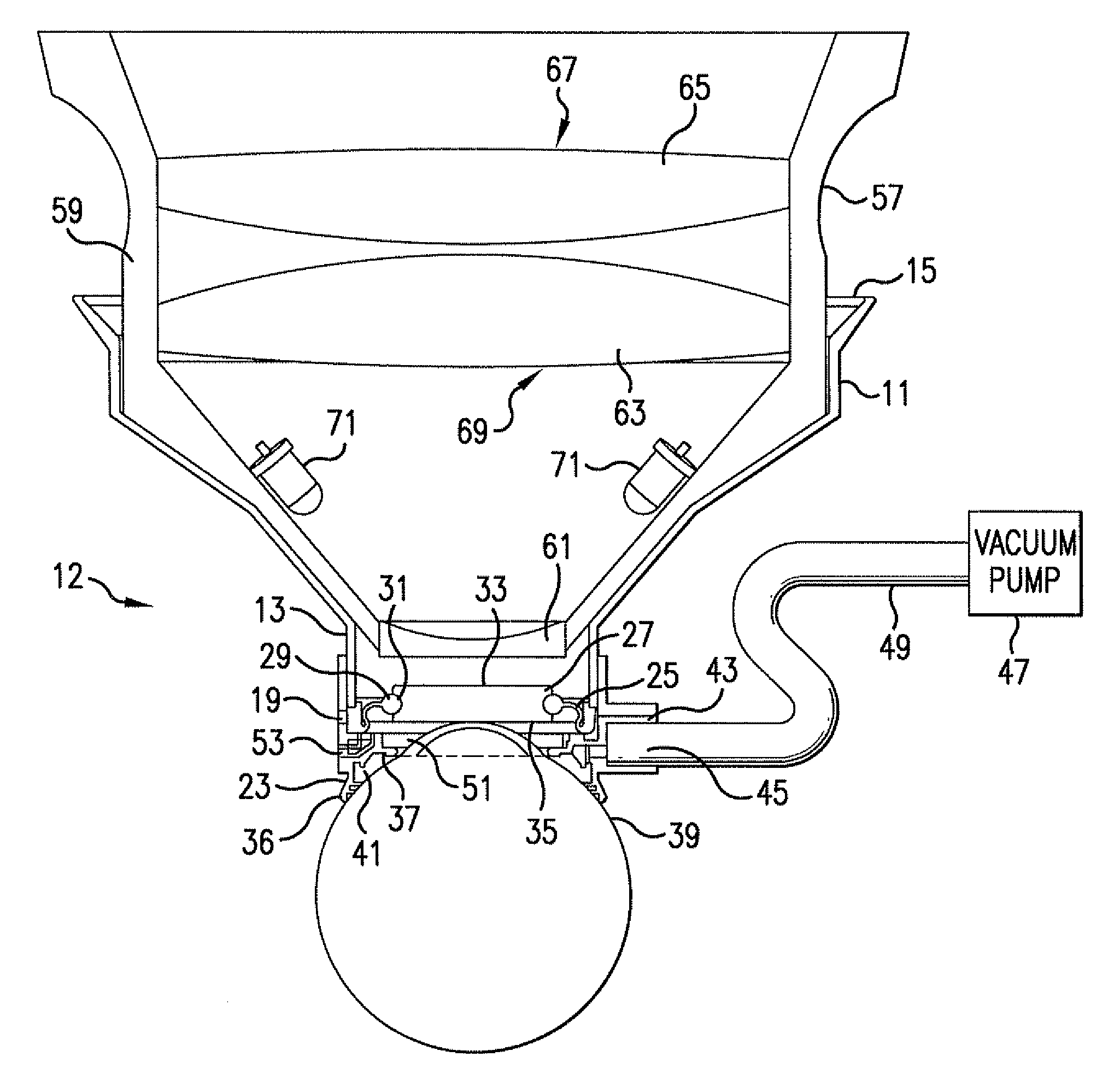
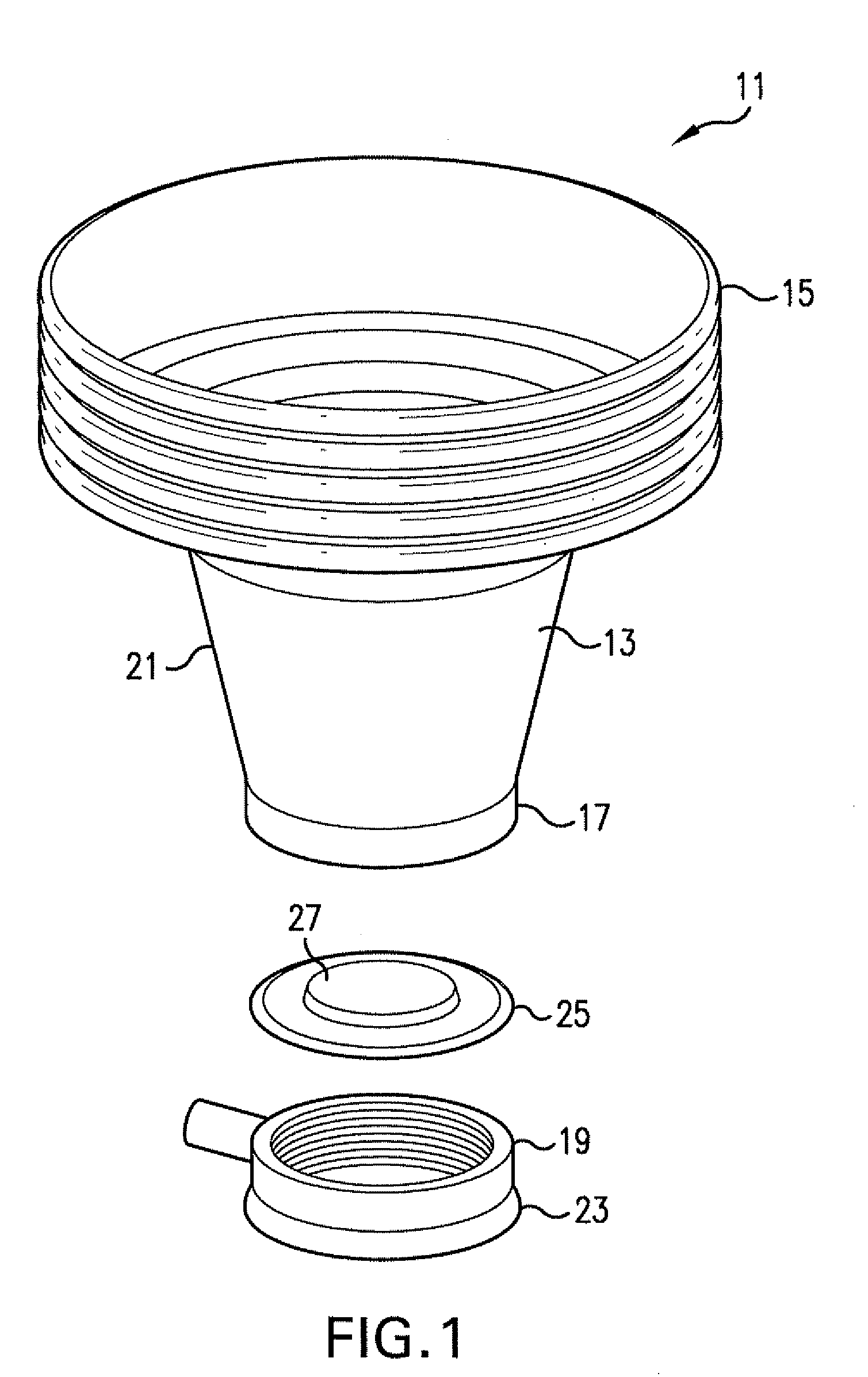
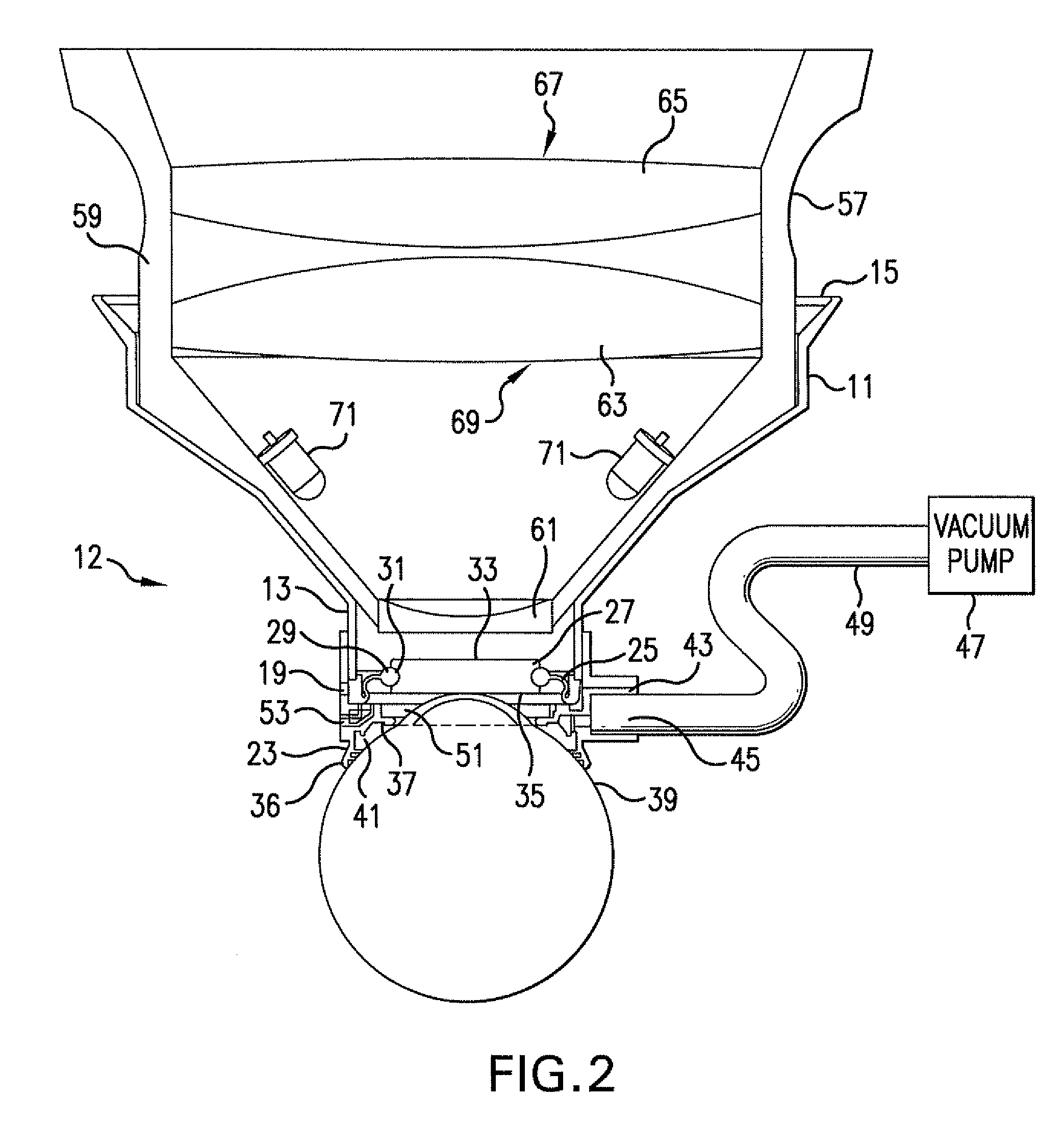
[0022] Apparatus, system, and method for interfacing an ophthalmic surgical laser system with an eye are provided having a centration aid. Generally, the centration aid assists in the alignment of an ophthalmic patient interface device (e.g., a disposable patient interface device or other patient interface device) with the cornea of an eye (e.g., for ophthalmic procedures utilizing the ophthalmic surgical laser system or to provide alignment of the ophthalmic patient interface device for other procedures). The centration aid is removably coupled with the patient interface device to facilitate alignment and the subsequent therapy utilizing the patient interface device. One example of a patient interface device is described in U.S. patent application Ser. No. 11 / 258,399, filed Oct. 24, 2005, the disclosure of which is incorporated herein by reference, although other patient interface devices may be utilized with one or more of the exemplary embodiments.

[0023] Referring to the drawing...


PUM


Abstract

An ophthalmic patient interface system includes an interface device and an ocular device. The interface device includes a frame having a first end and a second end, a lens disposed at the first end, and a skirt affixed to the first end. The second end is adapted to couple with a surgical laser system, and the skirt is adapted to seal against an anterior surface of an eye. The ocular device includes magnifying optics and is adapted to be removably seated within the second end. The magnifying optics image a region on a corneal side of the lens when the ocular device is seated within the second end.

Description

CROSS-REFERENCE TO RELATED APPLICATIONS [0001] This application is a continuation-in-part application of U.S. patent application Ser. No. 11 / 277,477, filed Mar. 24, 2006, which is a continuation application of U.S. patent application Ser. No. 10 / 865,165, filed Jun. 10, 2004, now U.S. Pat. No. 7,018,376, which is a divisional application of U.S. patent application Ser. No. 09 / 772,539, filed Jan. 29, 2001, now U.S. Pat. No. 6,863,667.FIELD OF THE INVENTION [0002] The field of the present invention is generally related to patient interface systems and, more particularly, to ophthalmic interface apparatus and system and method for interfacing surgical lasers with an eye. BACKGROUND [0003] Many advances have been made in the area of ophthalmic surgery in recent years. In particular, lasers are being used more and more frequently in certain ophthalmic surgical procedures. For example, an ophthalmic surgical laser may be utilized to remove cataracts, re-shape the cornea, or the like. When ...

Claims


Application Information

Patent Timeline
IPC IPC(8): A61F9/009
CPCA61B3/117A61B3/125A61F2009/00872A61F9/009A61B2017/306
Inventor LUMMIS, WESLEYRAKSI, FERENCKURTZ, RONALD M.
Owner AMO DEVMENT
Why Eureka
Try Eureka