Eureka AIR delivers breakthrough ideas for toughest innovation challenges, trusted by R&D personnel around the world.

Material-Working Machine

Inactive Publication Date: 2008-03-27
REINHARDT MASCHB
View PDF14 Cites 7 Cited by
  • Summary
  • Abstract
  • Description
  • Claims
  • Application Information

AI Technical Summary

Benefits of technology

[0007]The variable adjustability of the supporting unit provides the possibility for an operator to be able to operate the processing machine from the sides of the supporting unit, since, in the case of flat material parts of a small extent in the main feed direction, the extent of the supporting unit can be correspondingly reduced and, on the other hand, in the case of flat material parts of a great extent in the main feed direction, the extent of the supporting unit can be increased.
[0053]For this reason, the solution according to the invention proves to be particularly advantageous in the case of folding, since it provides the possibility of allowing the operator to operate, monitor and control the processing machine from the side of the region remote from the tool.

Problems solved by technology

They have the problem that, when a supporting unit of this type is provided, operating the material-working machine is ergonomically unfavorable.

Method used


Image

  • Material-Working Machine
  • Material-Working Machine
  • Material-Working Machine

Examples


Embodiment Construction

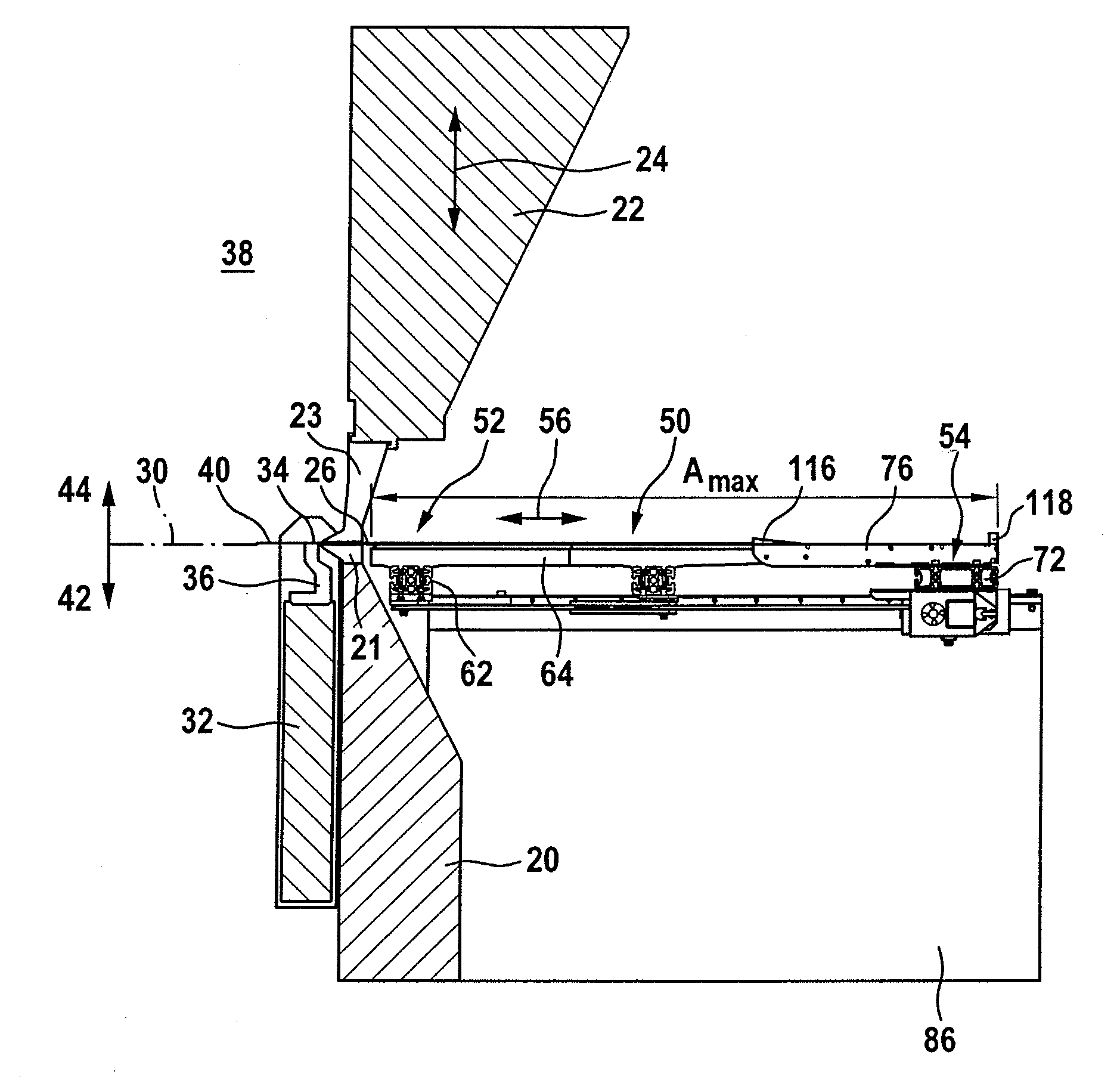
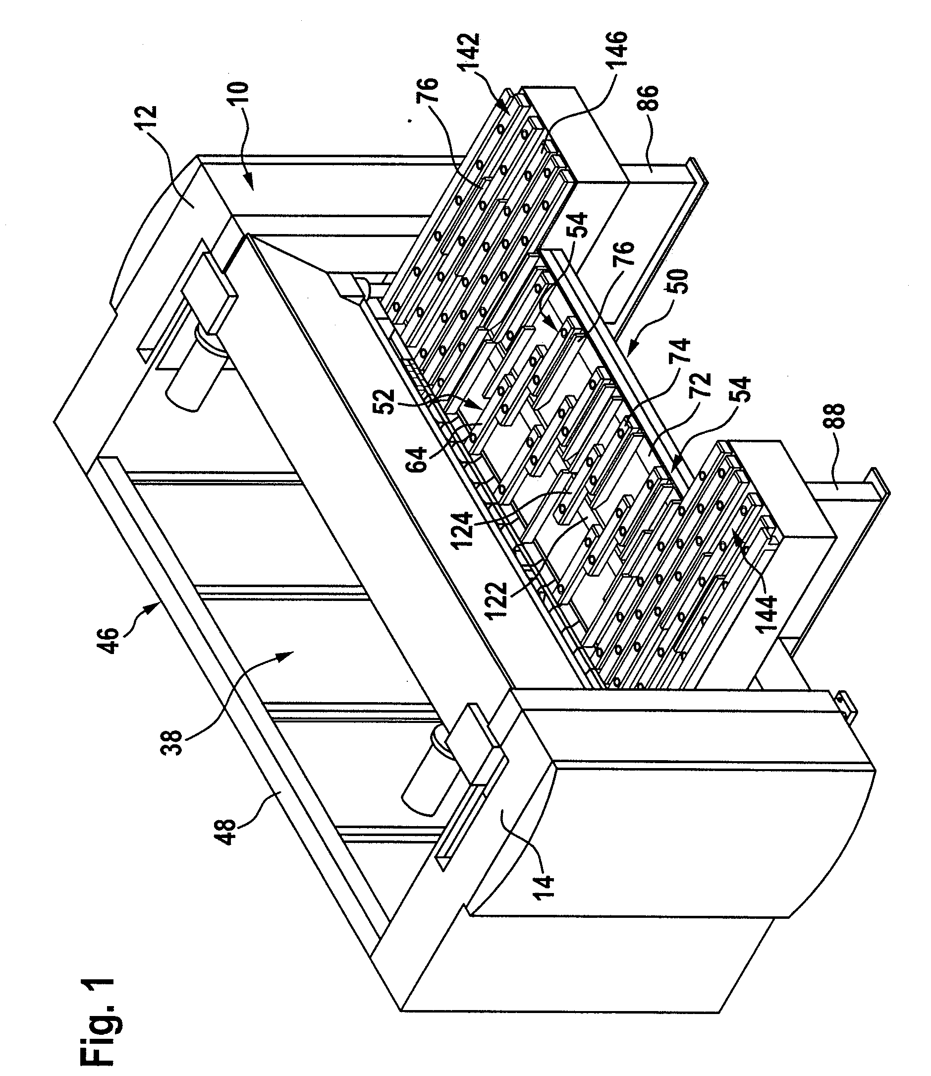
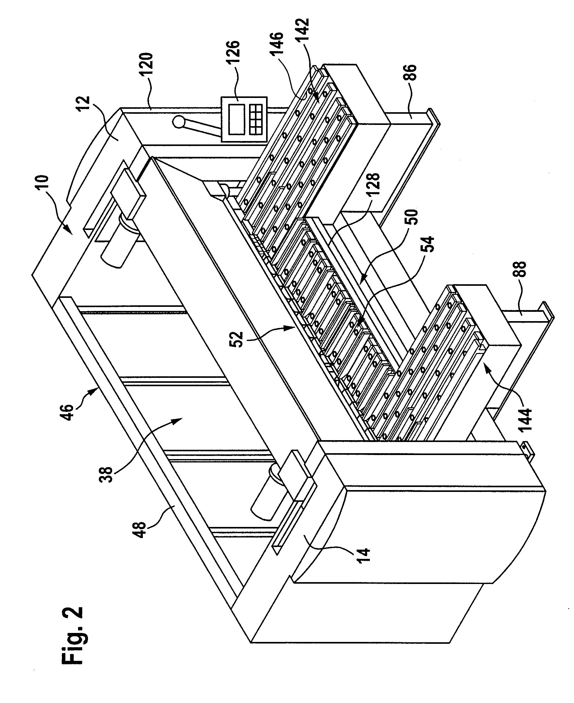
[0070]A first exemplary embodiment of a material-working machine, represented in FIGS. 1 and 2, comprises a machine frame 10 with two stands 12 and 14, between which there extends a lower beam 20, which is preferably fixedly connected to the stands 12 and 14, and also an upper beam 22, which is movable in a direction 24 relative to the lower beam 20, in order to be able to push a flat material part 26 in between the upper beam 22 and the lower beam 20 and also in order to be able to clamp it firmly between the upper beam 22 and the lower beam 20.

[0071]In this case, the lower beam 20 acts with a lower beam tool 21 and the upper beam 22 acts with an upper beam tool 23 on the flat material part 26, in order to clamp it in place.

[0072]The flat material part 26 can in this case be positioned and displaced in a supporting plane 30.

[0073]For bending the flat material part 26 clamped in between the upper beam 22 and the lower beam 20, a folding beam is provided, designated as a whole by 32,...


PUM

PropertyMeasurementUnit
Distanceaaaaaaaaaa

Abstract

In order to improve a material-working machine for flat material parts, comprising a machine frame, processing tools held on the machine frame, a supporting unit, on which the flat material part can be placed for feeding to the processing tools in at least one main feed direction, and a controller for controlling a processing sequence using the processing tools, in such a way that it can be operated in an ergonomically favorable manner, it is proposed that the supporting unit extends in the main feed direction from a region toward the tool to a region remote from the tool and that the extent between the region toward the tool and the region remote from the tool is variably adjustable.

Description

CROSS-REFERENCE TO RELATED PATENT APPLICATIONS[0001]This patent application claims the benefit of German Application No. 10 2006 047 109.1, filed Sep. 27, 2006, the teachings and disclosure of which are hereby incorporated in their entirety by reference thereto.BACKGROUND OF THE INVENTION[0002]The invention relates to a processing machine for flat material parts, comprising a machine frame, processing tools held on the machine frame, a supporting unit, on which the flat material can be placed for feeding to the processing tools in at least one main feed direction, and a controller for controlling a processing sequence using the processing tools.[0003]Material-working machines of this type are known from the prior art.[0004]They have the problem that, when a supporting unit of this type is provided, operating the material-working machine is ergonomically unfavorable.[0005]It is therefore an object of the invention to improve a processing machine of the generic type in such a way that...

Claims


Application Information

Patent Timeline
IPC IPC(8): B23Q1/25B21D5/04B23Q1/58
CPCB21D5/002B23Q1/58B23Q1/03B21D43/003
Inventor KUTSCHKER, WOLFGANG
Owner REINHARDT MASCHB
Why Eureka
Eureka Blog
Learn More