Liquid crystal display apparatus and driving method

a technology of liquid crystal display and driving method, which is applied in the direction of electric digital data processing, instruments, computing, etc., can solve the problems of lowering display visibility and difficult to recognize displayed images in dark places with less ambient ligh

Inactive Publication Date: 2008-03-27
JAPAN DISPLAY CENTRAL CO LTD
View PDF9 Cites 73 Cited by
  • Summary
  • Abstract
  • Description
  • Claims
  • Application Information

AI Technical Summary

Benefits of technology

[0013] According to a first aspect of the invention, there is provided a liquid crystal display apparatus comprising: a display panel configured to be formed by arranging pixels like a matrix; a light source configured to light the display panel; and a driving control means for controlling the display panel, wherein the pixels are transreflective type liquid crystal pixels having a reflective part and a transmissive part driven independently, and the driving control means is configured to separately control non-image periods of the reflective part and transmissive part.

Problems solved by technology

However, in places with bright ambient light, like outdoors, brightness is insufficient and display visibility is lowered.
Therefore, the reflective type is suitable for use in places with bright ambient light, like outdoors, but displayed images are difficult to recognize in dark places with less ambient light.

Method used


Image

  • Liquid crystal display apparatus and driving method
  • Liquid crystal display apparatus and driving method
  • Liquid crystal display apparatus and driving method

Examples


embodiment 1

[0029] Hereinafter, explanation will be given on a transreflective type OCB liquid crystal display apparatus (hereinafter, called a liquid crystal display apparatus) according to a first embodiment of the invention, with reference to the accompanying drawings.

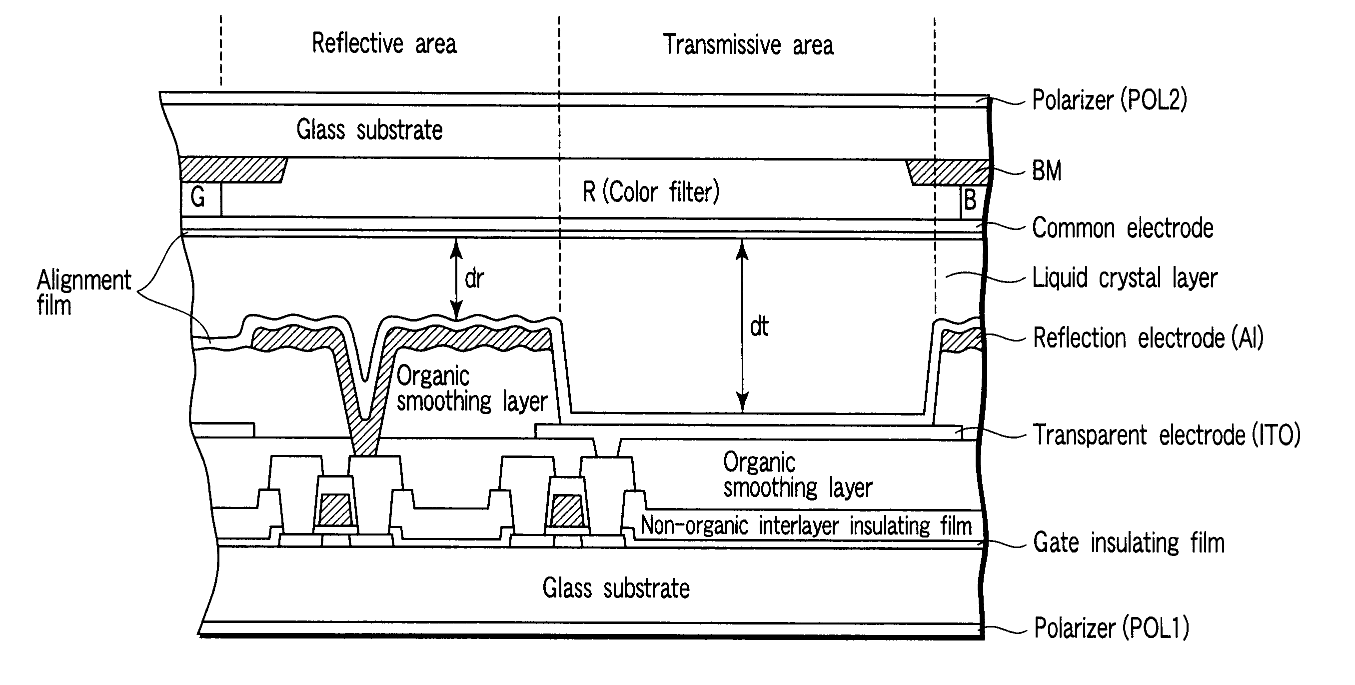
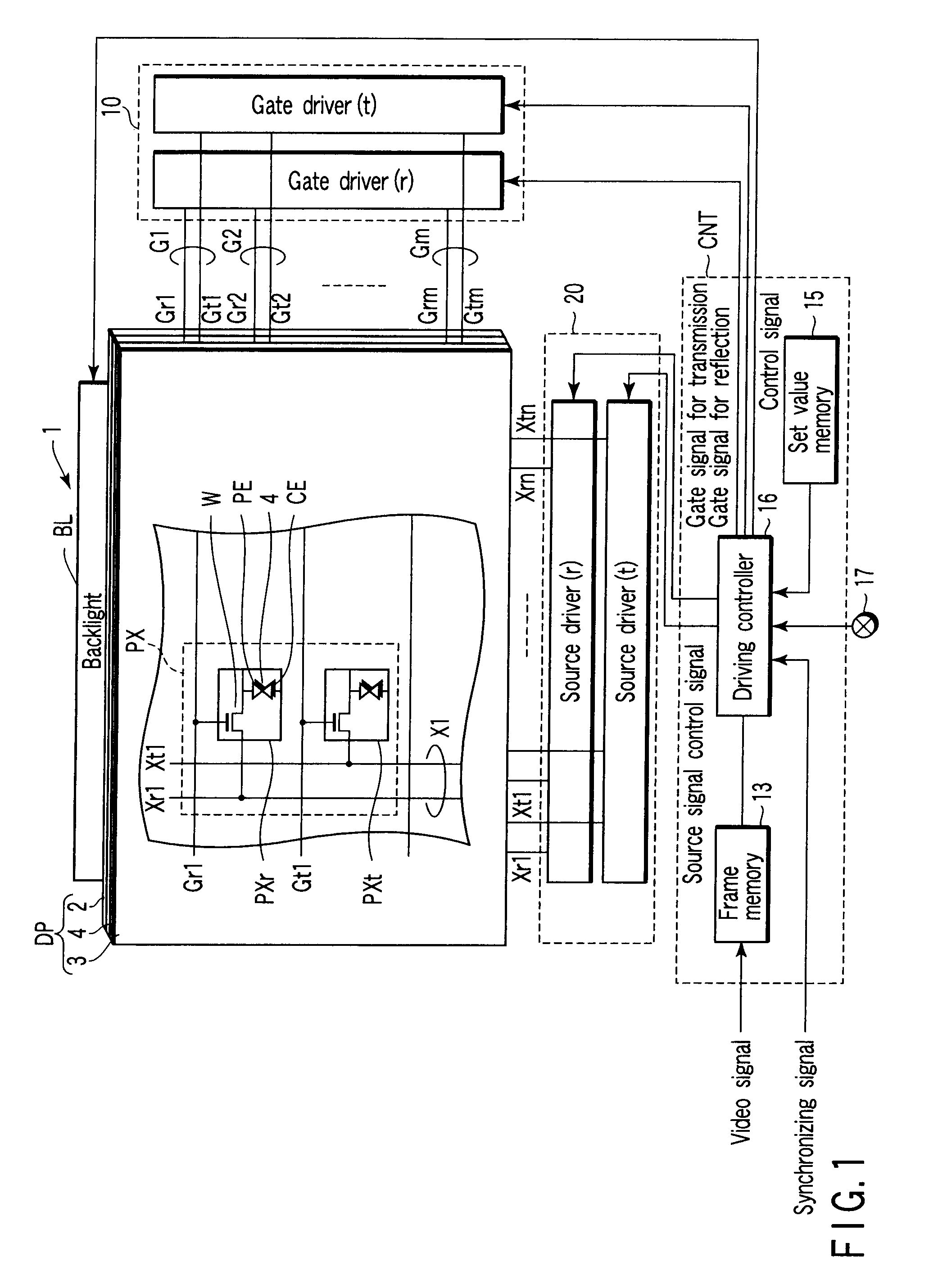
[0030]FIG. 1 is a schematic view of the circuit configuration of a liquid crystal display apparatus 1. FIG. 3 is a partial schematic sectional view of a liquid crystal display panel DP of FIG. 1.

[0031] The liquid crystal display apparatus 1 has a liquid crystal display panel DP on which OCB liquid crystal pixels PX are arranged, a display control circuit CNT which controls the liquid crystal display panel DP, and a backlight BL which illuminates the liquid crystal display panel DP. The liquid crystal display panel DP is constructed to have a liquid crystal layer 4 between an array substrate 2 and a counter-substrate 3.

[0032] The OCB liquid crystal pixel PX is a transreflective type liquid crystal pixel. Each display pixel is...

embodiment 2

[0083] A second embodiment is different from the first embodiment in the connection of liquid crystal pixel PX and source line X. Therefore, the same parts as those of the first embodiment are given the same reference numerals, and detailed explanation of these parts will be omitted.

[0084]FIG. 9 shows connection of liquid crystal pixels to a gate line and a source line.

[0085] The OCB liquid crystal pixel PX is a transreflective type liquid crystal pixel, and consists of reflective pixels PXr arranged in an odd line of the liquid crystal display panel DP, and transmissive pixels PXt arranged in an even line. Namely, the transmissive part and reflective part of the OCB liquid crystal pixel are configured independently in one pixel.

[0086] The gate line for transmission display Gt and gate line for reflection display Gr are connected to the OCB liquid crystal pixel PX, and drive the transmissive pixel PXt and reflective pixel PXr, respectively. In the first embodiment, the transmissi...


PUM

PropertyMeasurementUnit
gradation voltageaaaaaaaaaa
weightaaaaaaaaaa
light transmittanceaaaaaaaaaa

Abstract

A liquid crystal display apparatus includes a display panel configured to be formed by arranging pixels like a matrix, a light source configured to light the display panel, and a driving control means for controlling the display panel, wherein the pixels are transreflective type liquid crystal pixels having a reflective part and a transmissive part driven independently, and the driving control means is configured to separately control non-image periods of the reflective part and transmissive part.

Description

CROSS-REFERENCE TO RELATED APPLICATIONS [0001] This application is based upon and claims the benefit of priority from prior Japanese Patent Applications No. 2006-203861, filed Jul. 26, 2006; and No. 2007-182425, filed Jul. 11, 2007, the entire contents of both of which are incorporated herein by reference.BACKGROUND OF THE INVENTION [0002] 1. Field of the Invention [0003] The present invention relates to a liquid crystal display apparatus and driving method, and in particular to a transreflective type liquid crystal display apparatus and driving method, which is excellent particularly in moving image visibility and capable of realizing excellent display images without depending on ambient illuminance. [0004] 2. Description of the Related Art [0005] A flat-panel display device represented by a liquid crystal display apparatus is characterized by light weight, thinness and low power consumption, and widely used as a display device in a personal computer, portable information terminal,...

Claims


Application Information

Patent Timeline
Patent Type & Authority Applications(United States)
IPC IPC(8): G02F1/1335
CPCG02F1/133555G09G3/3406G09G3/3688G09G2300/0439G09G2360/144G09G2310/027G09G2310/061G09G2310/065G09G2300/0443
Inventor ARAKI, SHIGESUMINISHIYAMA, KAZUHIROOKITA, MITSUTAKA
Owner JAPAN DISPLAY CENTRAL CO LTD
Why Eureka
Try Eureka